Copyright © 2007 - 2026, Coachworks For contact data Click Here.
Copyright © 2007 - 2026
Copyright © 2007 - 2026,
Coachworks For contact data
Click Here.
![]()
Note that this is A WORK IN PROGRESS! Please write to share your comments.

Note that this work isn't intended as a criticism of what Porsche did but as help for those that follow, both those doing the work, thinking about doing it, or paying for it to be done!
Nor is this work about a historical or even practical dive into all one could say on the matter.
What this is about is a practical guide to actually solving the several bearing problems one encounters when rebuilding a 356 pushrod engine in the modern era because without properly done bearings, your engine isn't going to last very long.
There are more materials on this subject that we have already written up, buried somewhere on our web site, which we intend to provide here, so this page will be expanded as we have time to focus on it.
I've only been involved with these engines since the very late 1970s, and at the time was focused on the very early "two piece case" engines, and the very much younger C, SC, and 912 engines, and everything else was not something I was involved with. This remained true even when in 1986 I became an apprentice of David Brown of Weissach Engineering in Colorado Springs, and, later in 1989, Richard V. Lukes (of Lukes & Shorman fame) and in 1992 Red McCliontock, both in Berkeley... It was only in the late 1990s that I finally started to get exposure to the engines between these two extremes. And, just due to production numbers, what I haven't known about the engines in between is just a matter of both the statistics of production and that Porsche just didn't document a lot of detail that today we'd like to know about. And, of course, most of the original people involved such as Ritchie Lukes, are long gone now, so there are few we can get solid answers from.
Given this, I do not pretend to know it all. And, in particular, the starting and ending periods and the possible other varriations out there I haven't seen yet are all possibilities! ...Porsche had a bad habbit of superceeding parts without updating the part number and often wtihout any notice at all, so there's likely some detail that only the parts themselves can teach us. So, if you pick out something I've either gotten wrong, or that you can help clarify or fill in more information, please write me!
This might seem obvious, but given all the modern marvelous reproductions for the Porsche 356, one might get the wrong impression that if it's a part of the 356's past, surely someone makes a reproduction today, or at least knows about the stuff they are ignoring. Regarding the engines in the middle, this just isn't true! Further, don't assume reproductions are as good as the originals or old-school aftermarket.
Today, some engine bearings we cannot get new from current vendors at all:
- A and "Pre-A" rod bearings
- Eary 3-piece case main bearings that are lubricated via the camshaft's middle bearing.
- Second generation 3-piece case main bearings that are lubricated by one oil hole in the left case half.
- 3rd oversize on the case - in ANY type. (Why? This seems crazy to me!) However, recently (2021) we've noticed the German brand is offering a third over-size on the case (nominally 61mm OD) for the C, SC and 912 crankshaft type, but read below for issues we have with their bearings.
- 3rd undersize on the crank - in ANY type. (Again, this seems crazy to me!)
What's Made Today Isn't Always Well Made! Example: "German" brand main bearings

Beware of marketing material that claims to sell "German" main bearings! If modern, these are from a European company who has created a brand called "German." In our view, it's fraudulent marketing, but even if we're wrong about that, they are NOT made to original specifications!
What's wrong with these "German" main bearings?
The biggest problem of which we're aware is also the most obvious: they are made of steel instead of bronze backing material and so don't "crush" into the crankcase the same way. Further, the larger the outside diameter, the more likely that they just won't fit in a standard-cut crankshaft bore.
AT RIGHT: Here's our align-bore tooling. Our focus on it here is that we have two bars we like to leave set up, one at 60.5mm and one at 60.75mm (nominally), which are first and second oversize, tested and known reliable. Setting the cutters for a single cut is error prone as you only know you've "nailed it" when you use it and measure the results, and we're loathe to do this for a single case! ...Should we set up a bar or two, just for the German brand? -ugh!-
What goes wrong if you try and install them in a bore sized for original bearings? They may bind up and the crankshaft just won't rotate at all! Oops! This is a big problem. (See the images immediatley below for an example - those were 2OS-std German brand bearings for the C, SC, and 912 crankshaft.)
Notably, some workshops set up their boring bar based on the full-circle main bearing(s) (of which there are either one or two, depending on crankshaft type) that they find in the specific set of bearings sourced. This can be good practice if you can truly trust that the bore cut is going to be exactly as set, and our experience has proven that this isn't a reliable practice for a host of small reasons - and, of course, the devil is in the details!
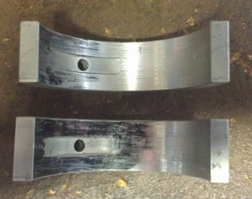
BELOW, RIGHT AND LEFT: Here's a "German" branded main bearing for bearing 1 that seemed to fit the case until the crankcase was torqued to a mere 15 ft lbs - the minimum our larger torque wrench will go - at which point the crankshaft seized. These images show what we found on the inside of the bearing upon disassembly.
The "rub spots" through the tin plating show where the bearing was being most clamped down upon. Note that the black tick mark on the outside face indicates where the dowel pin hole is, so these two pinch spots are right in line with the crankcase half seams - where the two halves come together. Careful investigation has shown that the reason it pinches on these two spots and not around the whole bearing is that the bearing doesn't want to "crush" into the case the way originally constructed bearings do and so the forces involved compel the pinching here, and the whole case stands a bit proud - that is, at this torque, the metal hasn't been forced together. This is good because having done so could have permanently damaged either the case or bearing.
It should be recognized that this pinching has also "used up" the 0.002" of oil clearance that's required, so these bearings are more than that much wrong! The solution was to cut the bore a very, very tiny bit more, but this is a delicate operation indeed! Better not to have to do it in the first place. So, if you can avoid the German brand of main bearing, do!
What if, after having bored the case bigger than the normal bore for whatever size it is, those bearings that were installed in said bore have to be replaced and the German brand ones aren't available in the size needed (or at all)? Well, you're going to have to bore the case again for whatever bearings you CAN get, wait until you can find another make of bearing in the size combination you need, or use a different case! ... None of these are attractive choices.
A quote attributed to Yogi Berra:
"It's amazing what you find when you look."
And so too, here; I'm sure many engines were put together with insufficient oiling due to missing the details presented on this page! And, one has to wonder how many engines were NOT reassembled when people who DID discover the details discussed here had no idea what to do about what they found?! And what to do about it is, of course, the point of this web page!
Unfortunately, people with 1955 to ~1959 engines simply have to be prepared to deal with the bearing problems identified here (or perhaps problems not listed here, in which case please write me!).
For the most part, this involves the reworking of bearings you can buy. If YOU cannot do this, then surely a competent machine shop, with these materials as a guideline, can!
Other than the change in the "standard case" (outside) diameter, all the important changes happened to the so-called "middle main bearing", bearing #2, which is of necessity a split (two piece) design, whereas all the others are a single-piece, full-circle type.
- Clearly, the earliest engines - the two-piece case series, from 1949 to November-ish, 1954 - had ordinary VW main bearings. These were solid AL (aluminum) with a tin-plated surface and a nominal OD of 60mm and ID of 50mm, with the exception of the nose bearing, bearing #4, which was, throughout production of all 356 pushrod engines, nominally 50mm OD and 40mm ID.
Oiling of bearing #2 was accomplished via one oil hole per bearing half, above the dowel pin that ensures the bearing is in the right location and doesn't rotate under any cicrumstances.
See any of the web pages for two piece case engines on this site to find example images.
- Most likely from the start of the three piece crankcase production, and surely by the time I rebuilt this engine, (1955 production 1500 S), the next version introduced a new nominal standard OD of 60.25mm while also introducing a change to where the oil comes from - namely, from the middle camshaft bearing, vertically up along a slot at the case parting line where the two halves join instead of from two round holes bored in to an oil galley deeper in the case (just where depended on the case era).
This change to the OD makes sense because it would help ensure that the older design main bearings weren't inadvertently fitted to the new 3 piece case engines since then they'd be starving bearing #2 of oil and fail prematurely.
- The third version still provided only one oil source but they moved it up to where the former oil hole had been previously. MY best evidence for when this happened was during "1958" production, which saw perhaps three completely different crankcase designs in about one calendar year!
These bearings and the case they fit are visible below and also on the web page for the engine rebuild whereupon I learned about this.
- The fourth version - I think it's the fourth version! - went back to the first design with two oil holes just where they were in the original VW design, but kept the later standard OD of 60.25mm. However, around that time, bronze (some claim steel, but I've seen the golden-yellow flakes of a copper-based alloy in damaged engines) backing material was introduced. CLEARLY, this had to be done at least on bearing #2 to support the new 55mm main bearing journals of the S-90, C, SC, and 912 engines! However, I'll leave documenting that to another day as these bearings cannot be confused for the earlier ones and they're all "the same" except for their inside and outside diameters, of course, as just like all the others, they have to match both the case and the crankshaft.
As described above, aside from inside and outside dimensions which must fit both the case and crank, these bearings came in 6 types:
- Early, 2 piece case, 60mm OD X 50mm ID standard, solid AL. (Left-most in image just below.)
- Early, 3 piece case, 60.25mm OD X 50mm ID standard, solid AL, starting for the '55 model year, lubricated from the camshaft's middle bearing. (Middle of the three bearings in the image just below.)
- Middle, 60.25mm OD X 50mm ID standard, solid AL, starting around '58 model year, lubricated from ONE half of crankcase - the left half. This introduced a new bearing to fit types 2 and 3. (Right-most in image just below.)
- Late, 60.25mm OD X 50mm ID standard, solid AL WITHOUT the notch to accommodate camshaft-based oiling. These are basically the first bearing (item 1 above), but with a 60.25mm OD standard. (Left-most in image just below - indistinguishable from type 1 here, except for the OD.)
- Late, 60.25mm OD X 55mm ID standard, AL and bronze (some say steel) "backing" inside to stiffen them, first introduced for the S-90, then used on both bearings #2 and #3 on the C, SC, and 912 engines. Image here.
- Late, 60.25mm OD X 50mm ID standard, bronze or steel backed like type 5, but for the 50mm journal crankshaft. (left-most in image just below - again, indistinguishable visually from the very first type.)
ABOVE: As noted in the text above this image, this image is sufficient to show what five of the six bearing types look like since several of the types look like the left-most example here. Unfortunately, the "spreader groove" for the left-most example isn't really visible in the above image, but we have this other image on this site that does: Click here for it. As noted, the middle one was used starting, we believe, in 1955, and the right-most example was introduced in 1957 for the 1958 model year.
 Probably
from 1955 Through to probably 1957, #2 ("middle") main bearing is
lubricated from the camshaft's middle bearing along the crankcase parting line.
Probably
from 1955 Through to probably 1957, #2 ("middle") main bearing is
lubricated from the camshaft's middle bearing along the crankcase parting line.Starting with the introduction of the three-piece 356 crankcase in 1955, the main bearings changed in (at least) two respects. The first was to increase the bearing's standard-size outside diameter by 0.25mm - this I am very sure about. For years I wondered why they'd done this and then I figured it out - it was done to help prevent confusion between the older "two-piece case" / VW bearings due to the second change: supplying the oil to the crankshaft from the camshaft middle bearings via a vertical notch machined into the left case half instead of more complicated diagonally drilled passages. This change in outside diameter makes sense because if the earlier type bearing is used without modification, the middle crankshaft bearing will not be supplied with any oil!
AT RIGHT: A close-up of an original middle-main bearing from the engine series in question in its installed orientation. Note the lack of an oil hole and instead how there's a notch at bottom with a groove to spread the oil around the bearing and get oil to the connecting rods. Also note the bevel at the upper end of the notch at the bottom - this is important as noted in the text.
This situation continued until the introduction of the B series, though I have not discovered a specific date or engine number - perhaps it's in Harry Pellow's books? Someday I'll look, but it's likely the change occurred with the introduction of the 616 engine series. However, this new-in-1955 strategy was later abandoned because it required pressurization of the lower through-bolt, creating a source for two potentially large oil leaks. They went back to the diagonally drilled oil hole, and at that point there was another new bearing.
Unfortunately, earlier and later bearings won't work without modification, though there have been main bearings manufactured that will work in any 356 (or 912) crankcase that runs an A or B type crankshaft - and these were an old-school after-market. The problem is that we're now, 60+ years later, in the reproduction era and not all reproductions have suitable oil passages for all the engines. Here, we illustrate modifying an earlier or later middle main bearing pair to fit these engines.
Since only the middle main bearings are involved here, we're focused on them, of course. The preliminary steps, before you can use the advice on this page, are:
BELOW: Another close-up image of the same bearing giving a little more perspective - again, note the bevel where the notch, now at left, meets the running journal.

Now that you know you need to proceed to modify your bearings, here a summary of the requisite steps - we presume here access to basic machine-shop tools. We will go through each step in more detail below:
 Secure
a cutter of appropriate with and diameter.
Secure
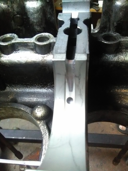
a cutter of appropriate with and diameter.AT RIGHT: Here's the bearing we created installed. Note the slot supplying oil from below (here "above") and no case hole matching up with the bearing's hole. Note that our new bearing has the beveling discussed in the text but because of the way we created our notch to receive the oil, the bevel doesn't widen at the notch, rather deeper in. (There's more about this in the text below.)
OK, now we go through these steps in detail.
 For
our cutter we chose a high-speed steel based keyway cutter of modest diameter
and size. The original piece has a 1/2" shaft to fit the quill, a thickness
of 3/16" (4.7mm), and a cutting diameter of 55/64", though the diameter
doesn't matter that much. In our experience with this cutter, we should perhaps
have chosen one with a little bit bigger diameter and maybe a tiny bit more
width, but this piece did a fine job.
For
our cutter we chose a high-speed steel based keyway cutter of modest diameter
and size. The original piece has a 1/2" shaft to fit the quill, a thickness
of 3/16" (4.7mm), and a cutting diameter of 55/64", though the diameter
doesn't matter that much. In our experience with this cutter, we should perhaps
have chosen one with a little bit bigger diameter and maybe a tiny bit more
width, but this piece did a fine job.
We then modified it by chucking it into an electric hand-drill and rotating it backwards from the cutting direction while putting the edges, one at a time of course, against a bench-mounted grinding stone, each rotating in opposite directions. It is only necessary to blunt the corners. The original bearing we had appeard to have been made with a cutter that had 45° bevels, so that's what we did, as can be seen here.
Here we presume that the reader is familliar with their milling machine and how rotary tables work. However, it's important to note that if you're using a drill press instead of a milling machine, you can still do the job with only a rotary table, but you'll have re-mount the bearing to present the flat end of the bearing for making the notch. Or, you can hand-file the notch, or create it by other means, as you see fit, but the same note above applies about avoiding 90° corners.
 By
mounting a bearing half on the rotary table with one end positioned more closely
to the center, one can cut a groove that becomes shallower as one rotates the
rotary table, and eventually vamishes. Simply having the intended start of cut
and end of cut be at different distances from center equal to the intended depth
of cut can ensure a perfect job
By
mounting a bearing half on the rotary table with one end positioned more closely
to the center, one can cut a groove that becomes shallower as one rotates the
rotary table, and eventually vamishes. Simply having the intended start of cut
and end of cut be at different distances from center equal to the intended depth
of cut can ensure a perfect job
AT RIGHT: Note how the bearing is not mounted concentrically, but is offset slightly - see text.
Because in all bearings one might modify there's an existing "spreader" groove, this can be exploited by cutting the end of the bearing that's closer to the existing oil hole and it's spreader groove. This makes the finishing of the new groove so much more perfect.
Note that the other bearing of the pair was used in clamping the bearing for cutting - they're the same height, so this guarantees a good clamping with perfectly perpendicular clamping forces. You don't want the bearing coming lose during this process!
The setting of the height is a snap for anyone familliar with a milling machine - just match the height of the existing oil-spreadder groove that all main bearings have and lock it down. And, because it's a rotary table, it's a snap also rotate the table to be aligned in the fore-aft direction and use the cross-feed of the table to move the whole assembly so cutting can begin on the flat end as intended.
A standard bearing is about 5 to 5.1mm thick and the measured oil spreader groove in our original had a maximum depth of about 1.5mm. It's our considered opinion that one should easily be able to get to 1.5mm depth, but one should not go as deep as 2.5mm for strength reasons as the original bearings of this era are solid aluminum with a plated coating. (B-era bearings have a bronze backing material and old repros and moderns could be anything - there's even steel-backed out there! And some, for sure, are also solid AL.) ...It's important to note that by connecting your new annular groove with the original already in your bearing, you're helping guarantee that the oil is spreading properly and you can be perhaps less concerned about the angle you put on your cutter back in step 2, and also the depth of cut as you taper out - so long as your depth isn't too shallow as you get well into the existing groove, you're doing fine, and so your setup can be a bit less paranoid about perfection.
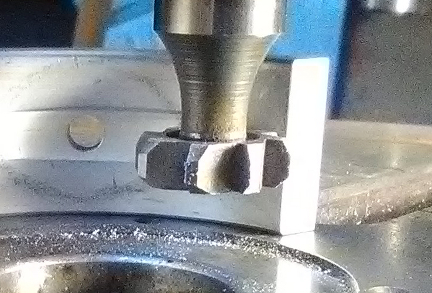
BELOW: Here we perform the cut. Note the bevel we've been talking about above is here clearly visible in the right-most flat end of the bearing and, indeed, in the cutting tool itself. Note also that this cutter cuts in a clockwise (from top) direction and so we're rotating the table into the cut. Often one might do it the other way, but in this instance we want to start the cut on the flat end for easy measure of our depth of cut - it will only get shallower from here - and we want to not be cutting into the flat end with the cutting tip as it could alter the position of the work piece.
Note that the slot in the rotary table that's nearest the flat end we started the cut at was originally alligned more or less exactly in line with the fore-aft feed of the milling machine's table. So, we started cutting the depth with a good idea of how far we were going just by feeding the table into the cutter, thus helping ensure we didn't go too deep.

We recommend returning the rotary table to the start position - just literally rotate it the other way and when at that point, you're damned near already set up for the next cut! All you need do now is rotate it "backwards" just a little more as appropriate for your diameter cutter to end up with this depth-of-cut where it belongs.
We recommend that you set your final depth-of-cut at or just a tiny bit less - and certainly NOT greater - than the notch depth in your crankcase. You can, of course, just plow through using the base table, however, when we do this we're a little shy about it and set the cutter spinning on the end, but not yet cutting, and then rotated the part into the cutter using the rotary table in order to get the depth we want. We can stop rotating, then feed the base table forward or backward to get the cutter out of the way and then measure, and then rotate back into the cutter deeper as needed. Sure, this takes a few more seconds, but it's easy and makes for a great job.

While original bearing sets had both sides notched like we're doing here in step 9, the case is only notched on the left half. So long as you're smart enough to install the notched bearing on the correct case half, you're DONE! ... HOWEVER, YOU MUST PROVIDE THE SPREADER GROOVE IN BOTH BEARING HALVES TO ENSURE THE ROD BEARINGS GET SUFFICIENT OILING!
Maybe now take another look at our finished and installed bearing up above, the third image in this section. Note how our beveled cutter makes for a very nice notch, and also notice how our cut vanishes as it approaches the oiling hole - it would have kept cutting until just past the oil hole if the bearing didn't already have a spreader groove...
As a final aside, the groove going around in such a relatively long number of degrees of rotation is helpful to feeding oil to the connecting rods and is the most important reason for having such a deep groove going around such a wide number of degrees - almost half-way. Not all bearings feed the rods as well as these bearings do.
If you've found this useful, it can't hurt to let us know! Now, here's a bonus image - an extreme closeup of our cutter, bearing mounted to the rotary table and, of course, the bearing's original oil-spreader groove.
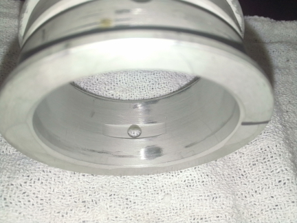
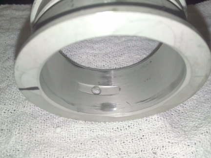
Starting in what I think was the "1958" model year, the middle main bearing was only provided an oil supply via the left half of the crankcase, as can be seen in the images here of case 6805x - note how there's a hole to supply oil to the middle main bearing in the left half but not the right (here, left is left and right is right):
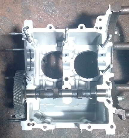
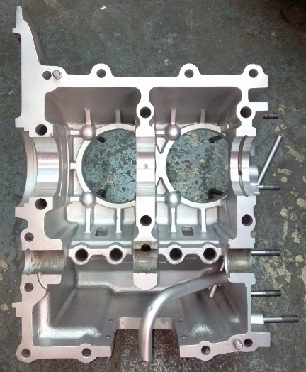
The original bearing that went here is the right-most one from the image above which includes three different middle main bearings, and also the next one below. I call this the universal bearing because it'll fit and work properly in any 356 with a 50mm based main journal. Note that in the instance where this bearing is installed in a case where the oil is supplied by the camshaft middle bearing, the notches are both installed down, and when installed in a later case with oil coming only from a hole in the left half above the pin (or, in even later cases with two oil holes above the pin, one in either half!), the notches are installed up, of course, so the bearing oil holes align with the ones in the case.
However, the previous build of the engine had the wrong bearings and seems to have survived on oil from only the left half, but then, it also didn't have very many miles on it at all, judging by the piston and cylinder set that were installed. So, maybe you can get away with that, but Porsche didn't try, and neither should you!
 Here
are the bearings that were made at that time. Note how they support BOTH (of
the then-only-two) three piece case middle-main oiling solutions!
Here
are the bearings that were made at that time. Note how they support BOTH (of
the then-only-two) three piece case middle-main oiling solutions!
What's vital about this type is the great rotational presence of the spreader groove that allows it to work on crankcases that have only one oiling hole! This one doesn't rely upon two oil sources, though it could have them like '59 and later cases, nor does it rely on oil from the cam bearing OR from just the left half - it can be used in any engine; THIS IS THE DESIGN THAT SHOULD BE REPRODUCED.
When working on engines of this type and these bearings are not available, the procedure described above for the fist three piece bearings may be applied to a suitable donor bearing, though of course the step creating the notch for oil to enter from the camshaft bearing - step 9 - may be omitted since you'll not be installing it in a case with camhshaft-based oiling for bearing #2!
The very long (rotationally) spreader grooves are manditory on these as otherwise the rod bearings will not be properly lubricated and the main bearing itself may not get proper lubrication!
This is an easy one! Thankfully, the available late-type rod bearings are functionally identical, they just have their locating tang on the opposite side of the bearing. So, what we do is simply notch the early rods for the late bearings!
First, to which rods does this advice apply? Well, while there are literally over a dozen different rods used in 356 pushrod engine production, including those of several different manufacturers that Porsche contracted with, they can be categorized into three groups: early, middle and late.
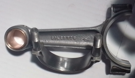
"Early rods" are from the start of production until the end of the A series. These are characterized by a narrow base (relative to the later ones), a thinner cap (again, relative to later ones), and a "locking tang" on the opposite side from all later rods. As we note elsewhere, it is our opinion that these rods are not fit for engines that produce "significant horsepower" or are used at the higher RPM ranges the later engines are known for.
"Middle rods" are really just "B" rods and are characterized by a wider base of the beam where it joins with the bottom end.
"Late rods" are like B rods but have a thicker - "full thickness" - rod cap.
These can be seen below.
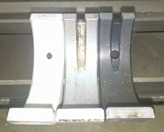
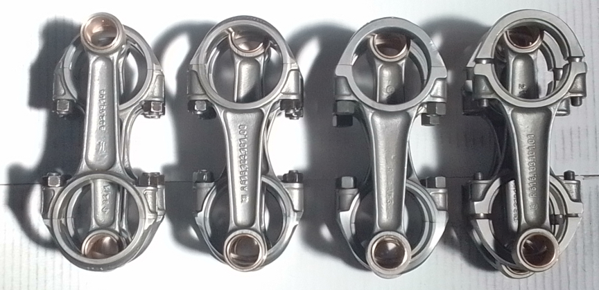
BELOW: The rods seen here reflect all the types of "plain bearing" connecting rods used in pushrod 356 engines. From the left, the left-most set is the earliest type, the second from left is the "middle" (or "B") version, and both of the right-most sets are the last type, used in C, SC and 912 engines - the very right-most here have rod bearings installed already! Note the forging numbers are visible for the curious. And, again, there were quite a vew versions of each fundamental type, making the matching of rods by weight a bit more challenging.
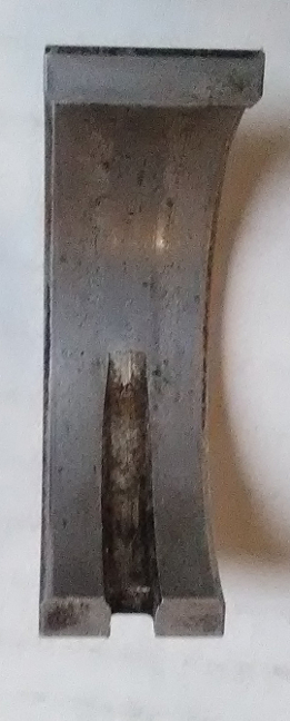
BELOW: Here we see the early rods notched on both the cap and rod beam. Can you tell which notches are the originals and which we added?
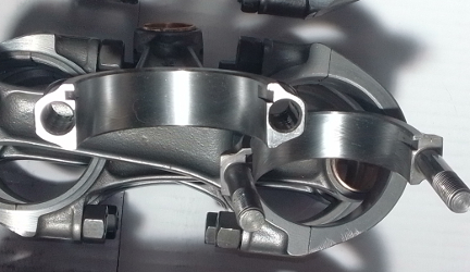
This is, of course, easily accomplished with a keyway cutter in a very similar manner as the main bearing modifications shown above!
If you send us a set of rods to be done - say, with your engine rebuild, for example - we will cut them for the late rod bearings as just a part of what we do since there's no point in having a rod for which you cannot readily supply bearings! ...Unless it's a part for your display case, perhaps!
Of course, we're here to help you with your project(s), and welcome your business.
