Copyright © 2007 - 2026, Coachworks For contact data Click Here.
Copyright © 2007 - 2026
Copyright © 2007 - 2026,
Coachworks For contact data
Click Here.
![]()
This page describes our Stuska, water-brake engine dynamometer.
Please note that this page is seldom updated while the dyno itself is undergoing constant attention and upgrades. ...We'd like to point out to the alert reader that if they look for differences among the images, they will find many changes - improvements - in our dynamometer, mostly not on this page, but between this page and the very many engines to be found of the "engines of our past" and other materials to be found on this site.
Also note that we recently, in 2021, have been asked to provide a book about our dynamometer and we have decided to share our own internal documentation and make a version available as a book we expect to be published shortly. It will be up-to-date and we will subsequently update this page. Meanwhile, please enjoy...

 Engine
dynamometers provide the opportunity to operate an engine under load. This permits
the operation of an engine under controlled circumstances which are analagous
to the engine's operation in service, with perhaps a bit more control than in
an actual vehicle. As such, dynamometers are very useful for a number of operations
pertaining to engines. These are the primary benefits:
Engine
dynamometers provide the opportunity to operate an engine under load. This permits
the operation of an engine under controlled circumstances which are analagous
to the engine's operation in service, with perhaps a bit more control than in
an actual vehicle. As such, dynamometers are very useful for a number of operations
pertaining to engines. These are the primary benefits:
Dynamometers are an indespensible tool in delivering engine excellence.
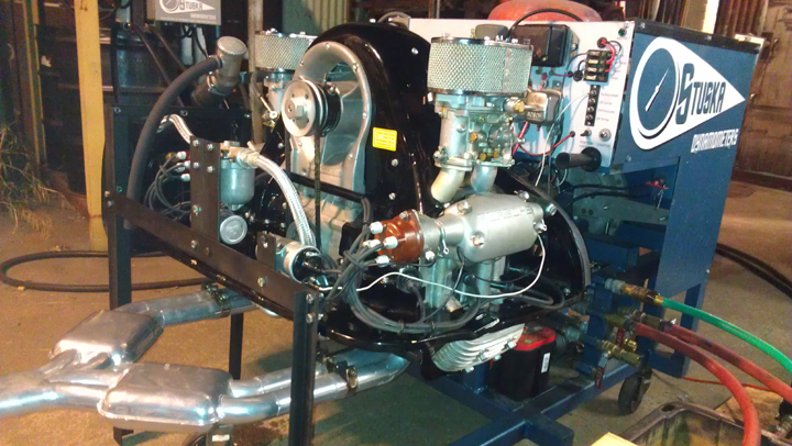
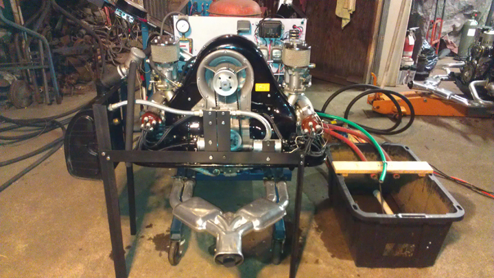 ABOVE
AND AT RIGHT: This 1500 GS Carrera engine ("4 cam") is being "run-in"
after assembly. Among the important benefits of this procedure are a longer-lived
engine, some modest leaks were found and fixed, and various adjustments made
such as carburetor jetting. Note that some engines, as with this Carrera, require
external support, in this instance including an oil tank (on left), the full-flow
oil filter (center rear), and a place for the twin ignition coils, so supporting
bracketry is used.
ABOVE
AND AT RIGHT: This 1500 GS Carrera engine ("4 cam") is being "run-in"
after assembly. Among the important benefits of this procedure are a longer-lived
engine, some modest leaks were found and fixed, and various adjustments made
such as carburetor jetting. Note that some engines, as with this Carrera, require
external support, in this instance including an oil tank (on left), the full-flow
oil filter (center rear), and a place for the twin ignition coils, so supporting
bracketry is used.
I can't wait until early Summer to swap out the SC engine for the 4 cam engine that you fixed. [Customer name withheld on request]
On this page:
 Running-In
Most dynamometers are designed to provide a load at and measure the peak torque and horsepower of an engine, however our dynamometer is special in that while it can absorb up to 600 horsepower, it can also provide a very small load which is required to run-in engines. Very few dynamometers can do this. Here we explain why this is important.
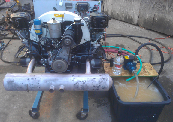
AT RIGHT: A Porsche 356 C engine mounted to the Dynamometer's Test Stand actively being run-in. The tub at right catches the brake-water output - it cannot be directly routed to return because that would alter the calibration. Intake hoses are black, outlet hoses red, and the vent is green. Engine controls and analog gauges are on the opposite side.
In the modern era we don't think much about "running-in" (sometimes "breaking-in") the engine of a new automobile but "back in the day", it was (and remains) a vital issue for the health and longevity of our Porsche, VW, and related air-cooled engines. Both Porsche and Volkswagen provided specifications for running-in their engines from the inception of those brands. Unfortunately, most shops don't have the required equipment, so most people have to do this function in-service. While it is important to "baby" any new engine for the first several thousand miles, no matter if it was run-in to specifications or not, when this service has not been performed on an engine, it is even more vulnerable to mis-hap and may not reach its full potential. The idea is to let an engines parts get used to each other and develop gently polished surfaces and otherwise let the parts mate together before putting them to hard service. This is important if they are to see their full expected service life.
As examples of these specifications, Porsche documented the required procedures for early engines in the 1952 Workshop Manual, as "Running-In and Testing" operations, 43 EN and 44 EN, pages E51 and E52. Later, in their still-available Workshop Manual for the B and C era vehicles, they documented running-in of younger engines as operations 52 EN, 53 EN, and 54 EN, pages E83 and E84. Similarly, we have researched the run-in specifications for all Porsches through the 911 series and all VWs through all air-cooled engines, and can provide the right service for each.
Generally speaking, the engine is run slowly at first with very low torque - so low that most engine dynamometers aren't even capable of providing a load that low. Then, the load is gradually increased over time, along with RPM. How much load at what RPM and how long it's run at each stage are what differ between engines.
In our service we start with a valve adjustment check and fresh oil and run the engine for a brief while checking basics such as ignition timing. Generally, we then change the oil before running the engine in - this is to get rid of any dirt and debris that was in the engine before starting the run-in process and there is always some foreign material left inside an engine during assembly, no matter how careful the engine builder. If it seems safe to run, we then run it in according to its particular schedule, and subsequently, when the engine has cooled fully, the oil is changed again and another valve adjustment is performed. Of course, the engine is checked for leaks, etc, and, if it's an engine we assembled, we correct any faults, or if it was someone else's work, we provide remedial service as per customer direction.
If we are performing the tuning service as a package deal, we will tune the carburetion and ignition timing using our 5 gas exhaust analyzer and a timing light. Our exhaust analyzer is from Bridge Analyzers, Inc, and we have the 900503 model. This capability is the fineist available; there's none better. We'll leave it to the Bridge Analyzers, Inc people to brag on their unit, however we did notice a web-site typo in the caption for the main photo of our unit (at the other end of the link above) - it says 4 gas. -shrug- In any event, exhaust gas analysis provides a powerful way to understand the operating conditions of an internal combustion engine - we've had our unit for about 5 years and have it serviced regularly. Lucky for us, their office is about four miles from our workshop, making calibration and securing new filters very easy.
This service should never be performed on a non-racing engine until after it has been fully run-in because it may shorten the life of a freshly assembled engine. This is because the engine is run to its very limit to get the maximum amount of horsepower out of the engine and that's not good for a brand new engine.
That said, our Dynamometer has a special feature that helps us reduce the negative effects of running an engine so hard; a computer controlled load controller with digial data collection. This means that unlike the days of old, we can do a "sweep" on an engine in just a matter of seconds. We don't need to write down numbers as in the old days. Instead, our digital data collection computer grabs all available data for us. It also has a built-in weather station, so we can give consistent numbers with correction for barrometric pressure, humidity, etc. There's more information on these points below.
Often, it is impossible to find a fault on an engine when it has no load. So, finding running faults is a key capability of a dynamometer; the engine can be put through its entire performance envelope under controlled conditions.
To assist us in diagnosing faults with our Dynamometer, we have some extra tools available. For example, we have a mechanics stethiscope which provides a method to hear the noises that come from inside an engine without putting the mechanics ears at risk. And, we have an infrared thermometer that can take temperature readings from a distance. These tools combine to help us find whatever fault may exist in an engine we're servicing.
Our dynamometer is designed to handle every Air-Cooled
VW and Porsche engine from the pre WWII prototypes to
the end of the air-cooled era, and perhaps beyond.
 About
our Dynamometer:
About
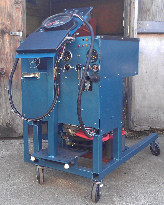
our Dynamometer:AT RIGHT: Test Stand with Control Stand stowed. This side has the analogue gauges, including two different tachometers (different ranges, one covering 4, 6, and 8 cylinder), two different oil pressure gauges (different ranges), an oil temp gauge, and hobbs meter. There's a coil voltage selection switch, various warning lamps, and four throttles (on right, below the gauges). On the Control Stand but not visible is the digital data collection system, though its display computer is visible below the large dial. Here, the Control Stand is undergoing rewiring.
Harvey Stuska of Denver, Colorado, developed a line of water-brake engine dynamometers in his garage in the 1950s. In the early 1960s, he was successful enough to incorporate as Stuska Engineering (as cast into the brakes, "Stuska Engg") and ran the business until about 2004 when Power Test Corporation, a Wisconsin company, bought Harvey's business. Power Test remains in business, fabricating new and servicing old water brake dynamometers under the Stuska brand name.
 Background
on Our Dynamometer
Background
on Our DynamometerIt's uncertain just when this particular dynamometer was made. It is clearly an early Model 300 unit, so named because its was designed to absorb up to 300 hp. Initial thinking from modern Stuska employees was that it was constructed between 1959 and 1961, and a re-evaluation of that suggests it may have been made as much as a decade later, but unfortunately it's just not known. Its original purchase history is also unknown but we do know that we got it from the rather famous Porsche 356 engine builder Harry C. Pellow in about 1995. It is known that neither Pellow nor either of hte immediately preceeding two owners ever had the dynamometer operational. Indeed, by the time we got it, all that remained were a few key pieces, and it was unclear that any of it had ever actually been put into service or not.
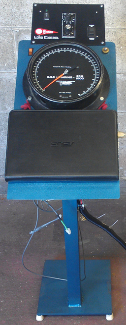
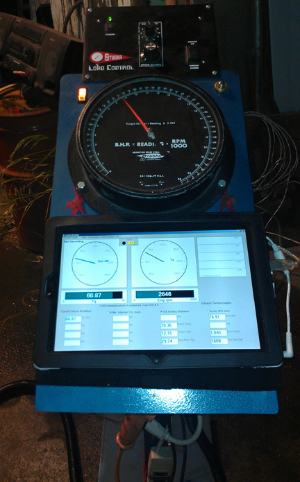
AT RIGHT: The dynamometer's Control Stand. The Stuska Digital Load Controller is at the top. Next is the old-school torque gauge, with starter on right, and lighted ignition switch on left. The next one down is the tablet computer that serves as a display for the Digital Data Collection system - the cover flips underneath to expose the display. A removeable keyboard tray can be installed below the tablet. Note this image was taken during reconfiguration of the wiring, hence the dangling wires.
Back in 1995, we contacted Harvey Stuska in Colorado who wasn't interested in helping put the unit into service, so we largely did it on our own, though later Power Test Corporation bought Stuska Corp from Harvey, and after that point we got great support from them. We managed to put the unit into operation in 2008. Since then, it has continually been upgraded.
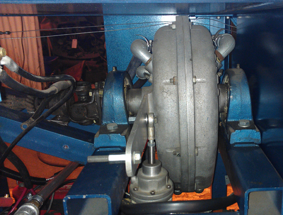
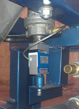
AT RIGHT: Here's the brake in a side-on view. It's mounted between two trunions (AKA "pillow blocks") that permit it to pivot freely. The torque arm comes toward the camera with the torque cylinder mounted on the inner fastening point via a heims joint so it pivots freely. The inner position permits better accuracy at lower torque values. The outer mount on the torque arm is used for calibration purposes. A coupling nut is used on both mounts so a level can be used to determine when the torque arm is level for calibration purposes. Above center, on both right and left sides in this image, the two 3/4" water inlets enter the brake at a 45 degree angle, and the vent is visible just below the inlet on the left. Several throttle cables - with no tension - are visible routed above the brake.
The first major upgrade, at the advice of Stuska Corp, was to open up more water ports to double the capacity of the brake, and provide a dedicated pump capable of flowing enough water to support 600hp. This, coupled with a radiator from a (railroad) locomotive engine, makes it possible for this dynamometer to handle the horsepower from most any air-cooled VW or Porsche engine ever sold.
 Our
Dynamometer's Capabilities
Our
Dynamometer's CapabilitiesOur Test Stand can accommodate, "as is", any air-cooled VW or Porsche engine because they all mount up to a transaxle using the same bolt pattern. To accomplish this, a replaceable bell housing from a type II VW which can be exchanged for other similar bell housings makes all the interchanges possible - most importantly, the varrious starters used. Additional support is provided by multiple throttle linkage setups and accommodation of the varrious fuel supplies, most if not all of the analogue gauges and electrical generation systems. (More on this below.)
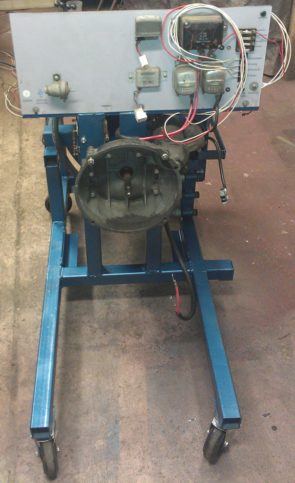
AT RIGHT: The engine side during a major reconfiguration (note wires on left). Far right, upper: Fuse block. Just below that: wires to engine. Moving left, voltage regulators for all the various 6V and 12V generators, then both versions of alternators with remote voltage regulation. On left, that's a throttle positioner diaphram from the "California SMOG" era. Below it, the 911 and 356 throttle linkage, and just left of center, the VW throttle guides. The bell housing is interchangeable with others to accommodate all engines.
To further the accommodation of "any air-cooled Porsche or VW engine," there's a new stand coming together (not shown) which supports the 911 oil tank and external cooler. Other adaptations are rather straight-forward.
Given questions the image at right may raise, note that the analogue gauges are on the opposite side of the stand than the engine mounting area shown at right. Available but not mounted to the stand are a plethora of other measuring systems, including fuel consumption, fuel pressure and a five-exhaust-gas analysis system from Bridge Analytics.
 High
Capacity
High
CapacityIn order to accommodate Any Engine, any load must also be accommodated.Originally this Model 300 was rated at 300 hp. However, we learned from Stuska Corp. that the brake was likely capable of more than double that if only one could get sufficient water through it. So, at their suggestion, we converted the former vent to a water inlet location, added a new vent, and added a new exit port at the bottom, next to the one original one. Thus, the water flow capabilities were doubled, and therefore the estimated brake capabilities were doubled, too. To further support this higher capacity, we have fitted a large primary pump to supply the brake, capable of 60 gpm at 60 psi - which is what's needed for 600 hp at the requisite pressure: One gallon per ten horse power minutes.
AT RIGHT: The original torque cylinder (above) and higher-range load cell (below) mounted one atop the other. The load cell is mounted on a "heims joint" so it can pivot in any direction.
As the brake's capacity was doubled, an improvement in torque measurement was needed, so the dynamometer now has three torque measurement devices installed: The original torque dial, a pressure transducer that's fed off the original torque cylinder, and a load cell - the latter two being read by the Digital Data Collection system.
The load of the engine is converted to heat by the brake, and if nothing is done, heat will build up in the recirculated water will eventually boil and cause difficulties! So we also cool the water with a huge radiator. It's literally 6 inches thick, almost exactly four feet square, has a built-in three foot bladed 5 hp ducted fan, and the manufacturer (C.H. Bull) says it is designed to dissipate 1200 continuous horsepower - so it should be adequate to this task! We may, however, not be able to flow enough water through it to dissipate that much! After all, it has three inch pipe fittings, and our primary pump only is a two inch, and our secondary ("return") pump has an even more modest capacity!
The model 300 is a bit of an unknown because it was designated at 300 hp before Harvey had truly tested everything or pushed them to their limits. But the model 300 is very close in design specificaiton to brakes that handle over 1000 - it only has half the water inlet and outlet capabilities - and for these younger brakes it is known that the water supply guideline is 1 GPM per ten horsepower at 60 PSI. Thus, (as noted above) our primary supply pump is sized at 60 GPM at 60 PSI.
The return of the water is more problematic. Generally speaking, return pumps aren't sized as large because test duration is typically short and a return pump can be returning water between test runs and because testing normally entails running up from low to high RPM, so a high load is not maintained for long. In our case, we had a return pump sized very close but it failed due to age. It is visible in photos here. We have since replaced it with a pump also very close in capacity (though not size). It probably can't match the GPM rate at the same pressure, but the return pressure doesn't have to be high, it only has to pump it back to the system. It's sized at 55 GPM, so in theory it could handle 550 hp continuously, which should be more than enough for these purposes. (Running-in of engines happens at a relatively low rate, in the few tens of HP, at most.)
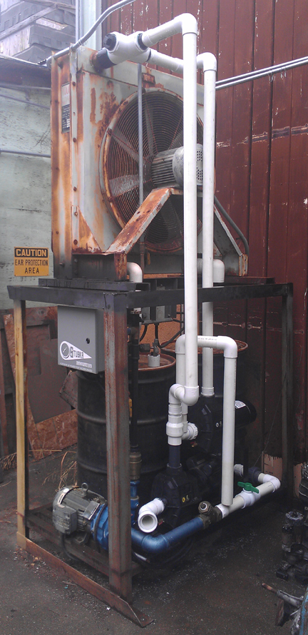
AT RIGHT: This image shows the water system in an earlier configuration than present but clearly shows the two 55 gallon drums are joined with 3" union at their base, the right one of which feeds the primary pump (in blue, lower left) via a 2" pipe (blue and white at bottom). The white pipe feeding the left drum is from the 1200 continuous hp radiator situated directly above the drums, so that is return water from the brake. The black pipe running vertically with a 90 elbow in the foreground left has been removed. The bronze fitting on the lower left is a check-valve on the primary pumps discharge, and the flow continues upward to a vacuum breaker (bronze fitting with chrome cap). Just below that is a T fitting with the original load valve repurposed as a controllable return-to-tank feature which permits the system to provide very low loading at low RPM when running-in small engines (like, say, 36hp VW) where the pump's minimum capacity may be too great. At the bottom of the image is the system's original return pump, since replaced with the new self-priming return pump. Also just barely visible at the bottom is the primary pump's feed, with filter (just right of center), and valve (green tip of wich is at the extreme lower right).
As can be seen in the image of the Control Stand above, we have chosen the Stuska Stand Alone Load Controller. This unit consists of two computerized units, an RPM sensor and some cables. The one computer controls the Primary water pump discussed elsewhere - a three phase unit capable of delivering 60 GPM at 60 PSI, and thus perfectly sized to 600 hp. The other computer provides the operator a dial to control load via engine RPM and a sweep-up and sweep-down rocker switch. The RPM sensor actually counts the straight-cut first gear teeth which were manufactured into our input shaft - which was originally a VW "split case transaxle" input shaft.
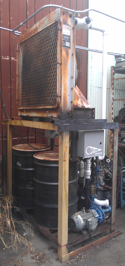
The radiator stand supports a 1200 continuous horsepower radiator which is roughly four feet square and 10" thick, and cooled via a ducted 5hp fan. Below this is a section where electrical connections are made and below this, three water pumps and two 55 gallon drums provide the water services the brake requires.
 The
grey and blue pump in the foreground is the primary pump that feeds the brake.
It is a three phase unit that is controlled by a computer inside the grey box
with the Stuska label which is, in turn, connected to the operator's Control
Stand - it only provides so much water as required to provide a certain amount
of braking, as controlled by the operator. The pump adjacent to the primary
pump (the center pump in the right image above) is the self-priming 2"
return pump that is operated by a float-switch that is inside the catch-basin
and is only needed for applications over 100 hp. (The brake is rated at 600
hp.) The third pump pictured above (right side of right image) is the radiator
recirculator pump and is turned on continuously to cool the water in the storage
tanks. In the image at right, its input pipe is hung to the right as a place
to store it, instead of into the 55 gallon drum because the drum's lid is installed.
The
grey and blue pump in the foreground is the primary pump that feeds the brake.
It is a three phase unit that is controlled by a computer inside the grey box
with the Stuska label which is, in turn, connected to the operator's Control
Stand - it only provides so much water as required to provide a certain amount
of braking, as controlled by the operator. The pump adjacent to the primary
pump (the center pump in the right image above) is the self-priming 2"
return pump that is operated by a float-switch that is inside the catch-basin
and is only needed for applications over 100 hp. (The brake is rated at 600
hp.) The third pump pictured above (right side of right image) is the radiator
recirculator pump and is turned on continuously to cool the water in the storage
tanks. In the image at right, its input pipe is hung to the right as a place
to store it, instead of into the 55 gallon drum because the drum's lid is installed.
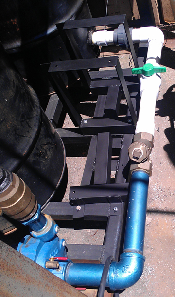
AT RIGHT: The two 55 gallon brake-water reservoir tanks are on the left, joined to each other near their base, the output of which follows through the white pipe, through the green-handled valve, the bronze filter, and then into the primary pump in the foreground (lower) left. In the space between the feed pipe and reservoir are the mounting locations for two large pumps (not mounted yet), the closer of which is the large return pump, while the upper one recirculates water through the radiator.
Of course, there are hoses used which are not attached in the images above.
The
...The Following is Under Construction!...
 Digital
Data Collection and Digital Load Control
Digital
Data Collection and Digital Load ControlOne of the greatest improvements we've made to our Stuska Dynamometer has been to incorporate a modern digital load control system - also made by Stuska! With it, the load can be controlled more or less just by turning a single dial. However, almost as important, we've also added a digital data collection system.With it, we get a complete weather station and real-time correction of torque and horsepower values as well as recording of most any engine-related data one can imagine.
Our digital data collection system consists of a data collection box, a "tablet" computer used as a display, and a handful of sensors. The data collection box is from Performance Trends and consists of their DataMite 3 with built-in weather station, and all of the sensors are also from Performance Trends. The tablet is from ASUS and was chosen because it has the right supporting hardware - USB ports, Wi-Fi, etc. The DataMite 3 is mounted on the under-side of the control stand, opposite the torque dial.
AT RIGHT: The Control Stand, in service. The dial in the center is the torque dial - and an original vintage component of this Dynamometer. The lit switch on the left is the ignition switch. The button opposite (on the right) is for the starter. The upper unit is the Digital Load Control unit and the computer screen below the dial is display for the Digital Data Collection system.
The digital load-control consists of two computers, one housed on the control stand just above the torque dial, and the other mounted in a grey cabinet directly above the primary water pump. The two are connected via a simple cable. The pump end is a three-phase motor controller, and the unit on the control stand sends it the right signal to varry its output based on the user's dial AND the engine RPM. It works to keep the RPM constant based on the dial setting.
We have expanded the capabilities of this dynamometer ever since we obtained it. By now, there are few additional improvements to make. One area that we have been working on is support for the external components. For example, in the two images at the top of this page you can see a stand we have created to support the 4-cam Carerra's oil tank, coils, and so forth. Similarly, we are in the process of supporting all the varriant 911s, including oil tank, external oil cooler and various fuel system compoents.
Ultimately, our goal is to fully support all engines that can be mated to this dynamometer, from pre-war VW through to the end of the 911 series and all variants, with custom-made stands to support all "external" components, as well as instances of these external parts so that we're ready to hook up any engine in a moment's notice without having to remove parts from a customer's car. And, we're doing reasonably well at our goal - feel free to contact us regarding your particular needs.
... Work in progress!...