Copyright © 2007 - 2026, Coachworks For contact data Click Here.
Copyright © 2007 - 2026
Copyright © 2007 - 2026,
Coachworks For contact data
Click Here.
 Porsche
Engine for Sale:
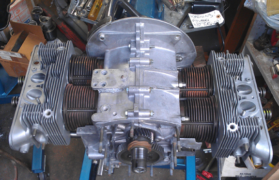
AT RIGHT: This engine, almost finished...
This 1966 Porsche 912 engine has just undergone a complete overhaul, and is fully balanced for smooth running, long life, and a few more HP. This page tells its story.
This engine is being prepared in long-block form. Note that it is also available complete, and the buyer has the option of having it run-in as per Porsche factory specifications on our Stuska water-brake dynamometer.
SPECIAL NOTICE
This web page is still under construction.
This disclaimer will be removed when the page is complete.
Meanwhile, the contents are reasonably accurate, just incomplete.
What of it is incorrect is essentially template material from a different
engine and is hopefully obvious.
ALSO NOTE
The 912 series can be used in a Porsche 356 (or VW) application,
however, the timing cover prevents the pulley sheet metal from fitting properly; a
conversion type timing cover is available that permits easy use in these
applications.
This 1966 engine came to us as a "core" and has just undergone a complete overhaul, and is fully balanced for smooth running, long life, and a few more HP.
This engine is type number 616/36 (912) and was originally constructed the late summer of 1966.
Of course this engine, as a 912 has all the features of a 912, often called "the late-type" in 356 circles, meaning that things like the oil pump, rockers, etc. are of the best (latest) design. During this rebuild it was fitted with 86mm pistons and cylinders.
This engine has undergone a thorough rebuild as described herein. Every detail about the engine has been attended to; nothing was ignored.
 Background
on This Engine
I received this engine among a group of cores from a single customer who purchased an engine and used the cores as partial payment. He is from southern Oregon and as I understand it, his father had run a small Porsche & VW shop in their rural community and these were things that were left over after he shut that business down some decades before. I met his father, then in his 90s, and he doesn't recall too many specifics any more. So, unfortunately, nothing further about this engine is known to us.
As described in the background section, the reason I received this engine from my customer was because they didn't trust the previous (just completed) rebuild. My customer paid me to disassemble and inspect the engine, and prepare an analysis which they might then use against the individual who sold it to them in support of their claim of fraud. Thus, my role was one of "expert witness." Because a case against the party that rebuilt this engine may yet be pending, it is inappropriate for me to get deep into details about the teardown.
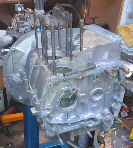
This crankcase required an align-bore.
AT RIGHT: The crankcase cleaned, inspected, and about to be align-bored. This was its first time, and it is now 0.25mm oversize - "first over."
I was sure I had taken some photos of the align-bore process, but somehow I didn't. I think the camera had a low battery and I forgot. Oh well. You can see something about that on other pages on this web site. If I think of it, I'll toss in a link here before I'm done.
 Well,
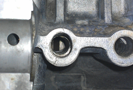
there was some fun and excitement, however, in preparing the case. I found that
the lifter bore for exhaust number four had a traumatic experience as though
the lifer was partially inserted and forced to go sideways. I can't think of
how this could possibly happen in an assembled engine, even if something horrible
had gone wrong because a lifter is some 60mm long and even at its deepest position,
it's still fully supported in its bore yet all the damage is in the top 10mm
or so. Its as if a lifter were barely inserted and something heavy struck it
from above, perhaps falling off a shelf..
AT RIGHT: Very curious damage at the top 10mm or so of the lifter bore of exhaust #4. Note how deeper in the bore is OK. How it happened is a complete mystery.
Whatever caused it, the damage was shallow, and the lower part of the bore went unscathed. A lifter inserted did ride OK in the bore and seemed well supported, and the lifter bore is some 50mm tall (about 2 inches) whereas the damage was only in the upper 10mm or so, roughly down to the cross-drilled oil passage. Here you can see it (above right).
 I
am VERY sure the vast majority of engine builders would have shrugged and installed
a lifter and moved on, however I'm not that kind of engine builder! Having been
here before, I realized it was pretty easily fixed by the creation of a lifter
sleeve. I first made an aluminum tube to insert, seen at left. I then centered
the damaged bore under the quill on my mill and bored out the hole to a larger
size and tapped in the sleeve.
The sleeve has to be an interference fit so it will stay put, and thick enough wall not only to keep that "crush", but also to take the lateral forces of the lifter. On the other hand, smaller is better to keep the strength of the original bore. After insertion, the oil passageway is reopened (from the cam gear end), and then the lifter bore reamed to size. Finally, a new "soft plug" is installed to close up the oil passage, just as was done originally.
AT LEFT: This aluminum tube serves as a lifter sleeve in the damaged bore.
 BELOW
RIGHT: Here, the repair is completed. Low in the image you can see the oil
passageway soft plug, installed. Just above the support for the camshaft, you
can see the repaired bore, ready for service.
BELOW: Showing the repair from another angle, with lifter installed.

Geez, wasn't that fun! Now that that distraction is dealt with, on to a thorough cleaning followed by assembly... Which reminds me: Before the new soft plug was installed, the case was cleaned and the passageway blown out with compressed air.
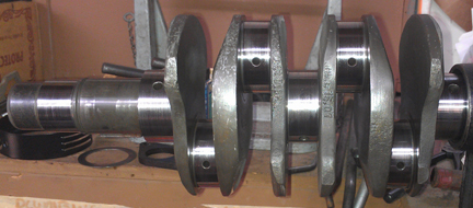 There
was no particular crankshaft that came with this crankcase so the one at right
has been provided. It was last in service in a C, even though it's not a C crankshaft
(it's an "SC/912").
AT RIGHT: Original crankshaft, "10/10", has been magnafluxed to check for cracks - it's in good shape. Note that the gears are not mounted in this photograph.
As usual, I mounted the crankshaft up on the ole crankshaft stand and mounted up the rods. The red mark (unfortunately not visible in the photograph here) indicates that I also magnifluxed the crankshaft to check for cracks and then rotationally balanced it!
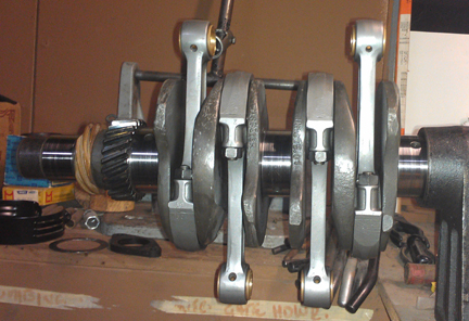 AT
RIGHT:Crankshaft with rods. Note that these rods were remarkably well balanced
as a set from new. Also remarkable is that Porsche used several manufacturers
and for whatever reason most "sets" were mixed from different vendors
and even different tooling from the same manufacturers, but these are all the
same.
I thoughtfully provided an awesome set of connecting rods. These are "late type", the best of the breed. I rebuild rods in batches - it's easier / faster / cheaper that way as it keeps setup time to a minimum.
For me, "rebuilding the rods" means to:
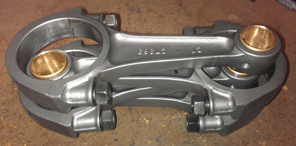 Magniflux
to check for cracks
This is all standard work so there aren't any photos of them in-process.
AT RIGHT: The set that went into this engine.
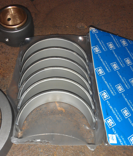
BELOW: I don't usually photograph the rod bearings, but here they are - Kolbies!
 Crankcase
Assembly
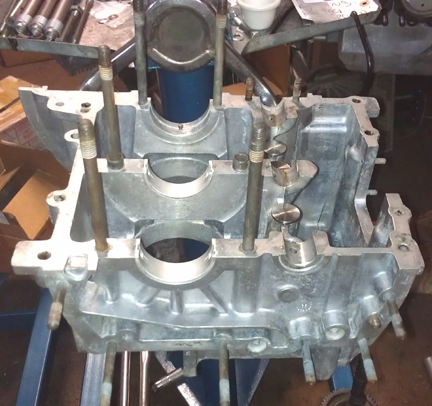
AT RIGHT: The left case half now ready for assembly, with bearing shells and lifters installed. Note that the lifters have been refaced. And yes, the crankcase does gleam!
By the time we get here, the case has already gone through cleaning and whatever machine work it may need, so here we should be ready to just assemble it all!
The case was align-bored for the first time (above)
Also worth pointing out here that I refaced the cam followers, just to be sure they wear-in correctly, and you can see them as the case halve go together...
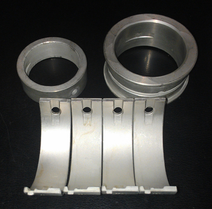
I don't usually show the main bearings, but these are the new "steel backed" ones provided by Stoddard (Porsche dealership).
 The
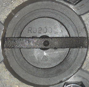
camshaft is an old-school "R0-200", the official wide-lobe replacement
cam Porsche was selling in the 1990s. I bought this cam new myself in the mid-'90s
and had it in a spare engine I kept around. It's only got a few thousand miles
on it but I refaced the lifters anyway, just to be sure they were the flat type
this cam profile requires (most require a slight dome on the lifter).
AT RIGHT: The gear end of the camshaft where the cam's grind is traditionally marked. The "R0200" was Porsche's wide-lobe SC / 912 replacement in the 1990s when this cam was purchased. Note the oil pump drive slot is nearly perfect, indicative of the fact that this cam has seen very little service.
The next step was to find a gear for the camshaft. They're sized of larger or smaller than a standard just called "zero." The range of available gears back in the day was maybe +3 to -3 from Porsche (or VW) and perhaps as big as +5 and small as -5 from aftermarket sources.
Today you're lucky if you can find any! However, pushing 30 years ago now I bought up a stash of twenty or so, and generally one comes in when another goes out. So, there is some modest churn in the stock. But what I have learned is that the gears weren't consistently marked between vendors, so one vendors +1 might be another vendor's -2. Strange but that's how it is.
In this instance, the first one I tried was the one stuck on the cam already, a -2. It didn't fit very well, a bit tight. I then tried all sorts of other gears, and found a -4 that almost works... After trying about ten, I finally fitted a brand new -5 which has the requisite clearance! (Note that if you can't hear / feel clearance between the gears, it's too tight!) At -5, it's the smallest one I've ever installed.
 AT
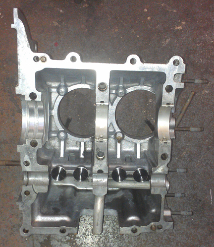
RIGHT: The right half of the crankcase, ready for installation, with bearing
shells and lifters installed. The lighting is poor, sorry, but you can see the
freshly cut cranshaft bore for bearing #1 (far left).
Now, time to put the case halves together!
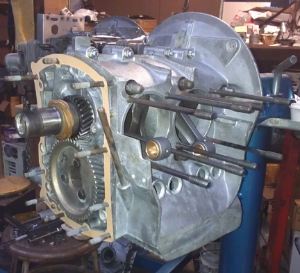
That goes rather quickly and here we have it as a "bottom end," sometimes called a "short block."
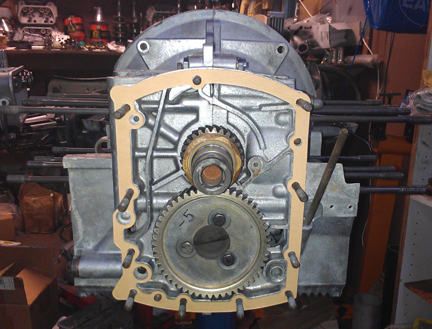
ABOVE LEFT AND BELOW: The crankcase now assembled into a "short block."
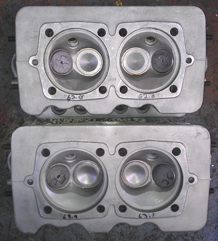 These
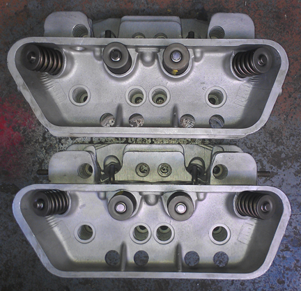
heads are a matched pair from a younger 912 and are in great condition! They've
never been cracked, still have their original seats. And, they have brand new
valve guides installed.
Fitted to these heads are great valves. They're originals, not aftermarket replacement which are all you can get new today. Further, and vitally, the exhaust valves ARE the sodium filled type, which haven't been available new for some years now. Of course, the valves have been checked for length (stretching makes them unworthy), polished, and refaced, so they're effectively perfect.
New springs, of course, carefully selected.
Every few months, we go through a large batch of about 40 new springs and group them by strength. First we match into groups of eight, then, with each group of eight, we match up slightly stiffer springs with the heavier valves (intakes are about 2% heavier than exhausts), so they're very close sets, matched up, so all the valves tend to float at the same time. ...Of course, each valve and retainer are position-specific through the shimming process...
Below: Here are some more photos.
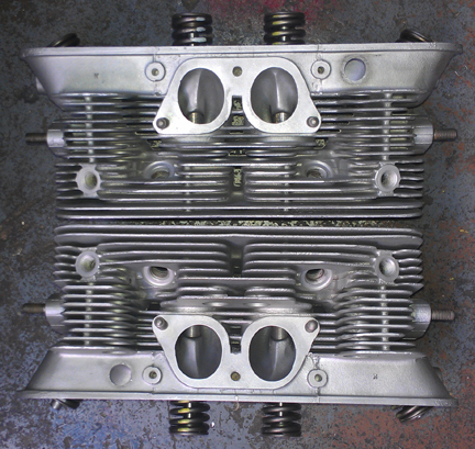
This engine has "NPR copies" installed.
<insert photos of pistons and cylinders being readied>
<more web page work needed here>
<insert photo of cylinder installed-height check(s)>
New parts are not exempt from careful checking!
We always check the match pistons to cylinders and match piston weights as a set, and provide any remedial action to correct any errors before installation. For example, by shuffling around the piston pins among the pistons, one can usually improve the matching of piston weights.
For many shops, from this point, installation goes very quickly, but we think this is where one needs to take one's time! The key reason one needs to take time here is that there are production tolerances on every part in an engine, and while a set of parts may look identical, there's often subtle variation between members of a set, and there are sometimes significant errors in production that weren't caught by the manufacturer's quality control processes. These errors can "stack up" and cause problems if not discovered and corrected.
<Insert photo(s) of the CAC check being made>
Here's our process: Two of these steps require special tools most shops don't have.
We like to carefully measure everything and then mix-and-match the parts for superior fit. We have also discovered significant manufacturing errors with this process which would likely have gone unnoticed without these measures. It is remarkably easy, for example, to overlook the circumstance of the crankshaft bore not in the true center of the crankcase, angled on the horizontal left or right of center, or not on the same horizontal plane at all. Yet examples of errors like these are not as uncommon as we would like.
<more web page work needed here>
The next thing we do is something nobody else does (that we know of) in the engine building process, and that is to measure the height the piston crown comes above the plane of the top of the cylinder. I call this the CAC, or "Crown Above Cylinder." This value is important because, firstly, it can reveal deeper problems, and because it helps us get the compression ratio equal in all four cylinders.
Here are some of the deeper problems that can be discovered through a CAC check:
In order to do this for these engines, you have to have special tools. Here, you can see them in action on this engine in the two images above.
<Insert specifics of CAC measurements here>The accuracy is so good, that if you take the time to swap parts around, you can accurately determine discrepancies in the manufacture of the various parts! But, we ARE splitting hairs here! However, a benefit to both engine builder and customer is that the ability to move parts around for better fit means that perfection is more easily achieved, and the more equal the HP production of each cylinder, the smoother the engine will run, and the more HP the engine will produce overall.
Because this process includes the entire assembly, torqued as in service, and measures the height each piston protrudes out of its cylinder, all errors in connecting rod lengths, cylinder heights, crankcase spigots depths (cylinder bore deck), piston connecting pin heights, and shim thickness' are accounted for in the measurement results. There is no superior method.
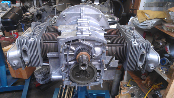 At
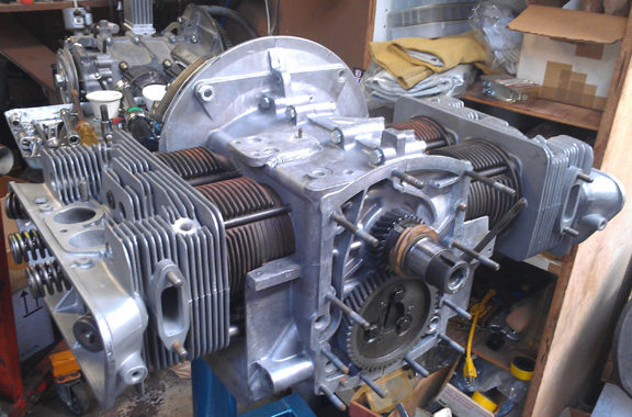
this point the engine is ready for its cylinder heads, and this work went very
quickly - as it should! - as all the prep work was already done.
Prepare the head "bolts" and washers, prepare the pushrod tubes, prepare the lower cylinder air deflection plates and their wire retainers, and get the torque wrenches set, and bolt on those heads!
My pattern is to mount one head, torque it to 7 ft lbs (as per the manual), then mount the other head the same way, and then alternate between the heads with an ever-increasing torque up to the final torque value, then repeat the final value until the fasteners no longer turn when torque is applied.
OK, mount the valve gear, adjust the valves and pop on the valve covers.
 Then
fit the oil drain plug, and sump screen and plate. Of some small note is that
all the sump studs are original and in fine condition. I used new cap-nuts to
protect the studs into the future.
Then, fit the two oil control pistons.
Can't forget the oil pump! In the images below, the cover for it is still in the parts washer - it should be gleaming just as much as the rest of the engine!
And now here it is as the longblock, ready for pickup or delivery!
NOTE: If this engine is sold as a long-block... One should NOT install the distributor drive gear without also installing a distributor because if anyone rotates the engine backwards, it will push the drive gear up where it can damage the bronze drive gear! Therefore, the distributor drive is NOT mounted until the last reasonable moment!
Because some people are keeping logs of VIN and engine numbers and then purport to tell people what someone else has, out of respect and concern for a buyer's privacy, exact VIN and engine number data are not published here.