Copyright © 2007 - 2026, Coachworks For contact data Click Here.
Copyright © 2007 - 2026
Copyright © 2007 - 2026,
Coachworks For contact data
Click Here.
![]()
The design and manufacture of tools is a rite of passage from apprentice to master; seldom are there true "mechanics" worthy of the name who have not made their own tools. So, naturally, one develops a collection that one has made over time. The better the tools, the better the tool-maker is likely to be at whatever else that person does. So, tools are a hallmark of engineering competence.
Here are some of ours.
NOTE THAT WE'RE REFORMATTING THIS PAGE AT PRESENT TO INCLUDE MORE TOOLS! This will take us some time; thank you for your patience.

 Contents
Here, you will find information on:
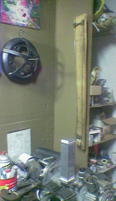
AT RIGHT: Here we have two of our tools we created decades ago. At left, in black, is our drum removal tool made from all disused parts, such as a bent rim. At right, on the wooden board, is our manometer. The main "body" of the manometer consists of vinyl tubing.
We make them because we need them, and because:
The contents of this page are sure to be far from complete, but we are starting this web page and are posting these images due to popular demand! Naturally, we are starting with the things people have just asked about.
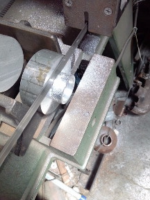
Begin at the beginning: The request that gave inspiration for this page was for an image of the manometer Richard made over twenty years ago - still providing service. While making a photo as requested, the drum puller constructed some years ago also came into view. In the image at right, the vertical board on the right hand side is the manometer while the large black disk on the wall is the drum puller. Note the 356 engine in the foreground for scale. (Please forgive the relatively poor image quality; it was taken with a digital camera in the low-light conditions of the moment. We'll try and remember to update the images soon.)
"Making tools is a part of the rites of passage from apprentice to master."
This tool has its own page! Find it here. We WILL merge it in here, but haven't done so yet!
This tool is already cited on another page. Find it here. We WILL merge that tool in here, but haven't done so yet!
Description
A drum puller is a device that assists in removing stuck brake drums. In our case, our tool is designed for the "wide five" VW bolt pattern, but the same principals apply to the design and construction of a puller for any particular bolt pattern. Note that this tool is especially useful on aluminum drums where any difficulty in removing a drum results in a situation where without a specailized puller, removing the drum puts the drum itself at grave risk.
Supplies
- 1 steel rim having target bolt pattern
- 1 piece of heavy gauge steel flat bar stock.
- 1 "square thread" bolt and matching nut
Construction
This particular tool was constructed from 100% scrap bits laying around the shop. The rim had been bent on the outer section that retains the tire. The flat bar stock came from one of the metal bows of a Karmann Ghia convertible top frame that had rusted solidly together and was to have been scrapped. And, the square thread bolt and matching nut came from an errant purchase at a tool store; it was a part of one of those "universal pullers" that has a dozen arms that bolt together and that never really works properly because there's too much slop in it - someone gave us the tool for nothing and it was repurposed here.
This particular square thread bolt, while adequate, should be considered the smallest one should use - its diameter is about the same as an early VW lug bolt. Go larger if you can.
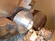
There are either three or four long weld beads holding the wheel's center disc from the outer rim that retains the tire. Use an angle-grinder with a coarse grinding stone to grind out these welds. The outer disc will separate more easily than one might imagine. Removing the hubcap clips, if any, is optional but a good idea.
As can be seen from the photograph at right, the bar stock needs to be cut into five equal length sections.
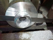
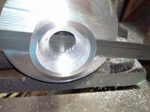
The female threaded section may need to be prepared for use. In this case, a circular piece of flat stock was used to mount the threads to by drilling a hole just barely large enough for the square threaded bolt to fit through, thus making in effect a large washer. The female threaded part was put on one side, the bolt on the other, and the bolt's shoulder against the washer-like piece was used to both square up the washer-like piece to the bolt, and center the bolt. Thus snugged, the female threads were then welded to the washer-like piece, and so the female threads now have a place to receive the ends of the 5 pieces of bar stock.
A spare axle was clamped vertically into a vice, a drum mounted as it would be (with the full stack of bearing and spacers), and then the wheel disc bolted to the drum. The square thread bolt was then threaded just a tiny bit into its threads and set upon the end of the axle. This setup was used as a guide for how much to curve the five interconnecting arms, and it guaranteed both proper centering and appropriate depth for the square thread nut.
Finally, the arms were clamped (with vice-grips) and welded, spaced halfway between each lug bolt hole. They were first welded to the center disc, all five, so that these arms could then receive a final adjustment on curvature. Then, they were tacked, and finally welded to the center disc.
Usage
When using this puller, one should always at least try to adjust the shoes inward. On many occasions in using this tool the brake shoes, and even the wheel cylinders, did not survive the operation. Also, the shoe retainers (the pins and caps) take a beating as well. However, when the reason the drum won't come off is because the shoes are rusted to the drum, this is expected.
On several occasions a modification to this tool has been considered in which an auxiliary component could be added to keep the drum assembly from turning as the square-thread bolt is turned, however, a crow bar inserted between the arms has always sufficed, though it tends to twist and move in ways that are not helpful.
Description
A Manometer is a device that measures relative pressures of gasses. In our case, we want to measure the depression (incorrectly called vacuum) difference between two intake manifolds of a running engine for purposes of setting the throttle plates as identically as possible. The more accurately they are set, the smoother the engine will run and the more horsepower it can create.
All manometers used for this purpose are to be fitted to a "vacuum port" between the intake valves and the butterflies, whether that port is on the manifold, a plate mounted below the carburetor, or the carburetor itself - the source of the depression does not matter but should be identical to all (read "both") carburetors (butterflies to be adjusted) in the system. The construction of that port is not a part of this description.
Supplies
- 1 piece of white pine, 1 X 6" X 3'
- 1 disused wire spool
- 4 brass hose barb fittings, 1/4"
- 2 brass "T" fittings, 1/4"
- 1 in-line valve, 1/4" (ball valve preferred - not fitted here)
- 10' of 1/4" vinyl tubing
Construction
The manometer is made of a white pine 1 X 6" X 3' board with clear vinyl tubing running vertically, looping under a disused wire spool at the bottom and fitting into some brass barbed fittings at the top where the crossover pipe and valve is located. One inserts some burnable liquid so that it reaches between 1/3 and 1/2 up the sides of the board. Tubes from there run to any "vacuum" port below the throttle plates of any two carburetors.
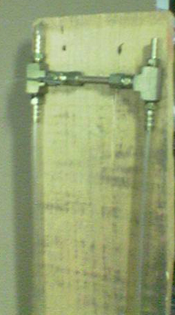
The image at left shows the top of the board where a "cross over pipe" joins the two sides and is fitted with a valve. This valve is a bit small. A better valve here would be a larger diameter ball valve, say a minimum of 1/4" should do. Normally, long leads of equal length run from the top of the vertically pointing barbs to each measurement port.
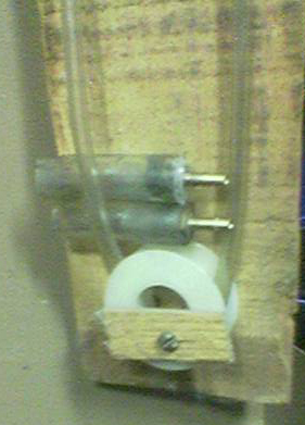
The image at right shows the bottom of the board where the tubing makes a "U-turn" down one side and up the other. The two extra parts stuck under the left tubing are adapters for fitting to a particular manifold; they are stored here with the tool. In this case, silicone sealant was used to attach the brass fittings to the hoses in an attempt to have an airtight seal. (It is effective, but one can easily overpower the silicone sealant when attaching or connecting these adapters, so be aware of the potential for leaks here.)
Note that except for the spool at the bottom, the pieces are attached to the board via strands of copper wire passed through holes drilled in the board. Feel free to improvise!
Usage
Prior to starting engine, fill loop of tubing in main body to not more than 1/2 of the height of the loop with some form of liquid that is combustible but not too toxic or hazardous. Parts washer fluid is often a good choice. Water or oil can be used but expect that occasionally some gets sucked into an engine and these two liquids will stall a running engine and cause difficulties. Then, attach both tubes from the top of the manometer to each "vacuum port", ensure the crossover valve is open and the hoses are fitted to their respective intake ports. Then start the engine. Finally, close the crossover valve. The manometer will now measure the relative difference in pressure between the two ports via the liquid in the system moving from one side to the other. You can then easily tell which port has more draw. Adjust your carburetor's butterflies accordingly.
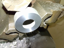
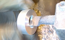
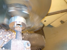
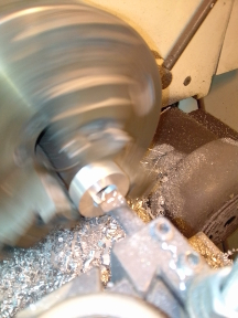
This web page is a "Work In Progress" but here are some images of this tool:
Here, ready for use:
Making the tool: