Copyright © 2007 - 2026, Coachworks For contact data Click Here.
Copyright © 2007 - 2026
Copyright © 2007 - 2026,
Coachworks For contact data
Click Here.
![]()
This page documents the servicing of one particular transaxle.
We were asked NOT to perform a rebuild if it could be avoided as the only thing known wrong was that one axle was stripped due to a drum having been run loose, and the opposite one was similarly damaged; both had to be replaced. And this is what we've done.

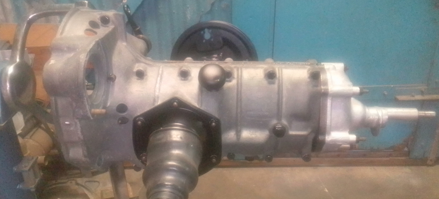
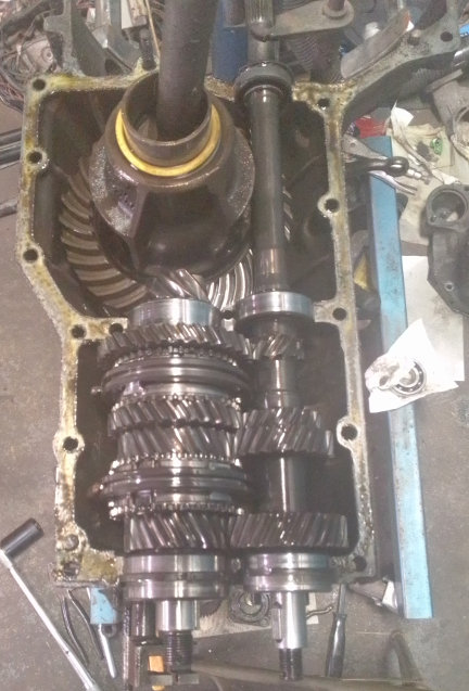
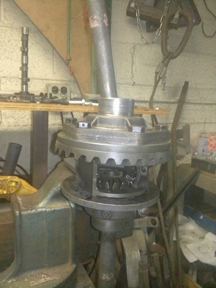
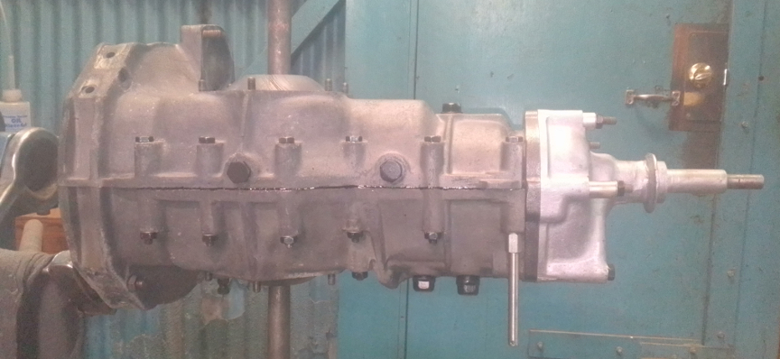
ABOVE: Here, the transaxle is almost finished, with plated hardware, powder-coated sheet metal, solid axle boots and more. below is the whole story, so far as we're aware of it.
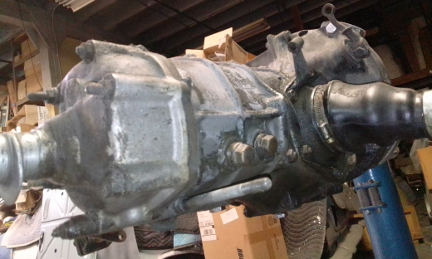
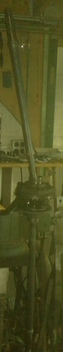
BELOW, LEFT & RIGHT: This transaxle almost as we received it. More details are provided below.
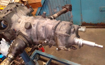
Our customer has a much earlier vehicle - we call 'em "pre-pre-A" because using a single "pre" isn't good enough! - and a more-correct transaxle for it, but this unit has been keeping the Porsche driveable, and needs to keep doing so until the more-correct unit can be rebuilt. The reason it was brought to us was that unfortunately someone didn't torque the rear drums properly - or, perhaps, it wasn't the torque, per-se but maybe the mating surfaces in the "drum stacks" weren't perfectly clean, smooth and parallel - we don't know which. Either way, the drums were shifting back and forth on the axle splines until one of the drums hub's "let go," making the car inoperable. Investigation showed the other axle was similarly aflicted and would fail soon, so both axles have to be replaced. It was also known that the shift fork adjustment access hole plugs were weeping oil.
 The
guts, however, were unknown; we were asked to not do a full rebuid if it could
reasonably be avoided since there's another, more correct transaxle coming.
The
guts, however, were unknown; we were asked to not do a full rebuid if it could
reasonably be avoided since there's another, more correct transaxle coming.
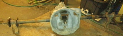
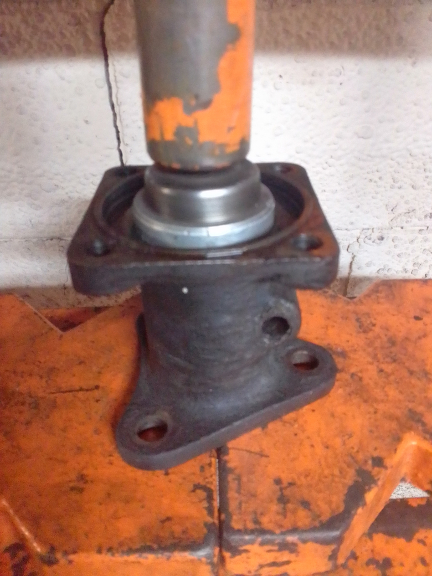
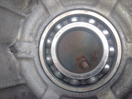
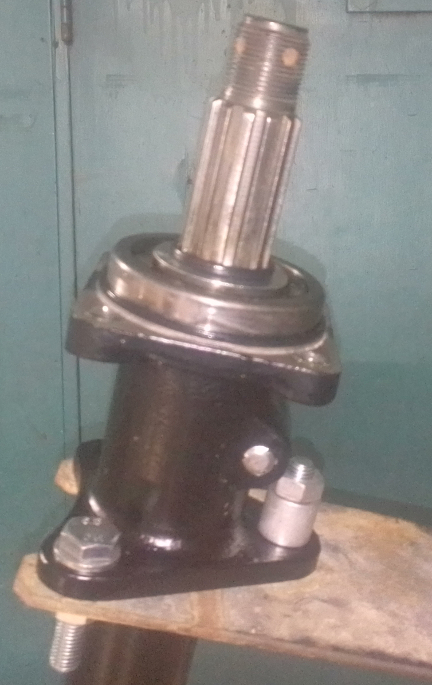
AT RIGHT: The donor VW unit the day we received it. Unhappily, this unit has been left, as you see it here, outdoors for at least 6 years. Considerable rust was visible holding the outer axle bearings in.
Knowing the unit needed both rear axles and knowing there was commonality with the similarly aged VW, our customer brought us their 519 unit and another, "36hp" era split-case VW unit for parts. While we got "before" pictures of the donor unit immediately upon receipt, unfortunately we didn't snap similar "before" images of this 519 unit immediately upon delivery. Thankfully, though, we did take some shots once it was up on one of our factory transaxle rebuilding stands - they are above.
In the following materials, many small steps are not mentioned for brevity's sake.
Step Zero is to remove the gear oil, and do a major de-gunking of the exterior with plastic scrapers to avoid damaging the metal. Most oil was drained out before we got it, but there was still a fair amount left inside. And, the scraping process began before the two "before" images above were taken. However, initial observations included that when this 1956-era 519 unit was applied to the current service in a much earlier car, the studs on the intermediate plate for the former mounting style were left in place and thus various spacers were used due to length differences and one stud was not really sufficiently long, just barely holding a nut. The current application requires a rubber bushing that wraps around the input selector shaft as the "nose mount:, while the "single mount" (the second mounting system version) bolts to the trans using the "cover" (AKA "nose cone") mounting studs - the very studs just cited. And so the nose cones differ and thus the stud differences as well, even though they're both 519 transaxles. (The third and final version, "dual mount", uses a yet differently shaped casting with two "rubber doughnuts", one per side.) ... Since the transaxle is only in temporary service in this particular vehicle, no changes here are contemplated.
BELOW, LEFT AND RIGHT: Here the outer axle bearings were removed using the youngest type of factory wheel bearing removal tool which superceeded the earlier type, VW 241 T. This tool is FAR superior, and we've created a tools web page that shows the tool in more detail. You simply clip the collet into the bearing - it inherently wants to lock into the inner race - then thread the long, larger diameter section down onto the collet that locks the collet fingers into the inner race, then turn the locked assembly into the inner section to take up any slack, and finally the long threaded bolt is tightened which pulls the bearing out. It may seem complex, but it's really simple, elegant, and vastly superior to any other method of bearing removal. (The same company makes similar bearing pullers for many applications.)
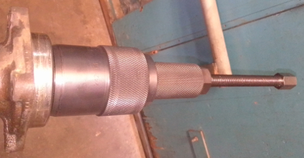
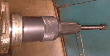
While we see the outer wheel bearings here removed very easily, the same wasn't true for the donor VW unit. ... Unfortunately, there are two instances where it can't work. First, if the fool who installed the outer wheel bearing used a non-stock bearing which doesn't have an available gap for the tool to lock into, it can't work - but then, for such bearings, the VW 241 T won't work either! Or, in the case when the outer race is rusted deeply into the axle tube end casting, which was the case with the donor VW united pictured above, the tool is far more valuable than, in this case, the VW axle end casting and when it appeared this special tool just wasn't going to defeat the rust, the solution was to ask permission and then use a 5 or 7 pound mallet and two people to drive the axle tubes, with the bearing, off the assembly. This worked, but not without a heck of a lot of pounding!
 The
nose cone (AKA "transaxle cover") then had to come off, followed by
the intermediate plate. There wasn't a good spot to stop and take photos until
the reverse gear parts were taken care of. Unfortunately, once the intermediate
plate came off, we were too focused on other things and didn't get a photo of
it with just the intermediate plate removed. However, note that to get the intermediate
plate off, either the cast part the gear selector shaft uses to select reverse
has to be removed, or the whole reverse selector shaft has to be removed to
provide access to the nut found behind it, and also to just get the intermediate
plate off the studs..
The
nose cone (AKA "transaxle cover") then had to come off, followed by
the intermediate plate. There wasn't a good spot to stop and take photos until
the reverse gear parts were taken care of. Unfortunately, once the intermediate
plate came off, we were too focused on other things and didn't get a photo of
it with just the intermediate plate removed. However, note that to get the intermediate
plate off, either the cast part the gear selector shaft uses to select reverse
has to be removed, or the whole reverse selector shaft has to be removed to
provide access to the nut found behind it, and also to just get the intermediate
plate off the studs..
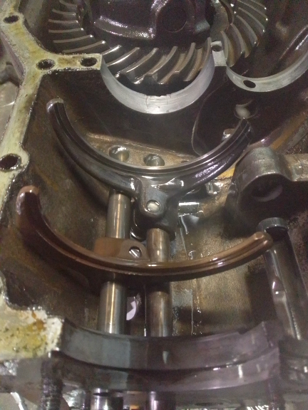
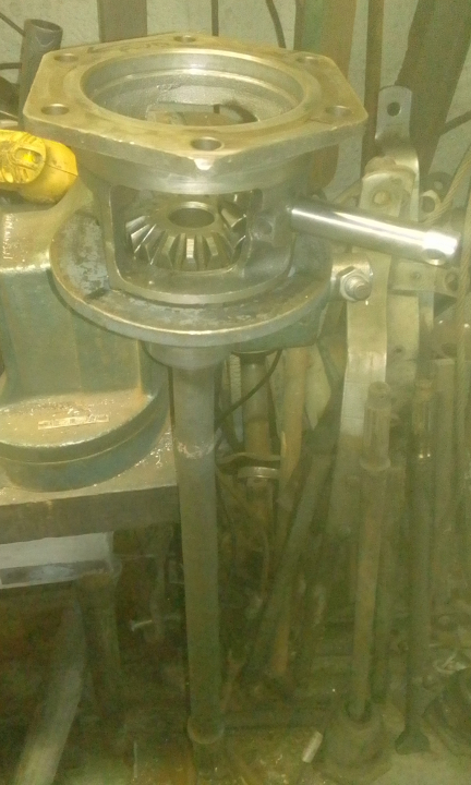
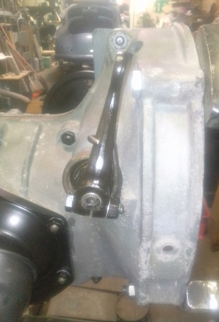
AT RIGHT: Nose cone removed. Note that to remove the intermediate plate - the steel surface that's bolted on to the two magnesium case halves with four nut showing - you have to either remove the "foot" for the reverse gear selector shaft, or, just remove the whole shaft, as is shown here. Please see text for more.
At this point, the caes is split.
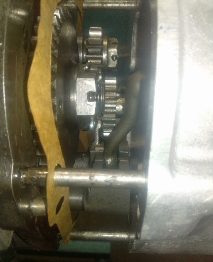
BELOW, LEFT: The right case half was just removed. BELOW RIGHT: The input and pinion shafts have been removed. Note the cracks in the pinion shaft's bearing bore directly adjacent to the ring gear! More on that below.
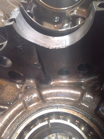
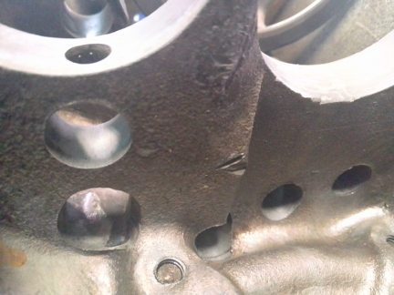
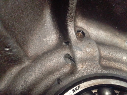
BELOW: Apparently, the differential lost a bolt or bolt head or some such and it rattled around below the ring gear. It's impossible to know what happened exactly, but we do have experience with these things. Here's imagery of the damage - we've seen WAY worse still in service! These are just dings, except for the cracks in the bearing saddle - more on that below.
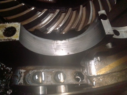
AT RIGHT: Note the first of the dings we're showing, on the wall above (here left) the center of the pinion shaft saddle. Again, more below. (The right case half had no such damage.)
Our diagnosis of the cracks in the pinion bearing saddle bore is that it makes little - maybe no difference. This is because at that exact point, all the stress is away from the cracks! Engine power is trying to drive the pinion shaft away from the ring gear and to the extent that it can't move away, it drives the ring gear in rotation. Additionally, it does not appear as though they have propagated since the impact that created them.
However, this is 2022, and this box was made in 1956, so, given its age, there's no telling how many miles it has or anything like that, so we do not warrant these cracks won't propagate someday. We're just saying that economically, keeping this unit together makes the most sense since, so far as we're aware, though Porsche originally made these from VW castings, nobody has ever actually taken a VW casting from a completed VW unit and converted it for 519 specifications. Surely it's possible, but, again, the economics argue against trying.
At this point, the disassembly continued until completed, and we spent some further hours cleaning the case, and then transitioned into reassembly before taking the following images. However, logically these belong before we document the reassembly process.
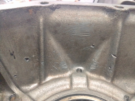
BELOW: For more images of the impact damage by whatever was floating around in there. These are far more common than we would like, however, these transaxles (and especially the younger ones using an aluminum casting instead of magnesium) usually continue on without notable issue.
We took apart the axles, both to check them for straightness and to be able to most easily install solid axle boots, as original, without risking tearing them by stretching them over an end-bell.
BELOW: The axle tube is shown here being pressed out of the late 1952 end-castings that they were mounted to. This was for several reasons, including checking the axle tubes for being straight, and to make installation of the solid axle boots quite easy.


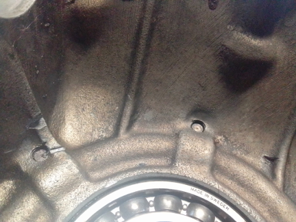
AT RIGHT: After washing, we were greeted with finding the cause of the weeping selector shaft adjustment bore plugs - note the thread damage seen here in BOTH bores! Ouch! (Some people just shouldn't sell their services as mechanics!).
And, oops! We apparently didn't get photos of the differential disassembly process. However, on reassembly, we've got quite a few.
And now, of course, we transition into reassembly.
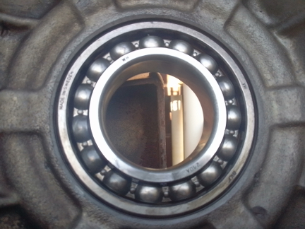
BELOW, LEFT & RIGHT: Here are the side bearings, S1 and S2, ready for more service. Note how the one side has 15 balls while the other has only 11. This is because the thrust side, the S1 side, takes more of the loading from the engine and, in particular, outward axial thrust, and so more balls means more surface area and so it handles this load better while the other side doesn't need it.
The differential carrier is very often cracked. While they can crack just because they're iron and not steel, we believe most cracks are from unskilled workmen of the past.
AT RIGHT: Here's the completed reassembly of the differential, now lacking only the lacing of the bolt heads with so-called "safety wire."
Unfortunately, the factory manuals show someone using a lead hammer on an axle end to drive the whole assembly out. Apparentely, many workmen don't realize the hammer is supposed to be a VERY soft lead and just use an ordinary steel hammer. Thus the shock cracks the carriers at the spider shaft.
AT LEFT: Here, the spider gear shaft is being installed as the differential is going back together using all the same parts - except the axles of course. The only difference in this assembly is that the side gear and fulcrum plate parts have been swapped side-for-side to flip the thrust to the least worn surfaces.
Also unfortunately, the factory used a "pein in place" process for the spider shaft's lock pin, and one bad blow during peining can crack the carrier.
On the former, we have invented our own tool to avoid doing this, and in the latter, we use a roll pin instead.
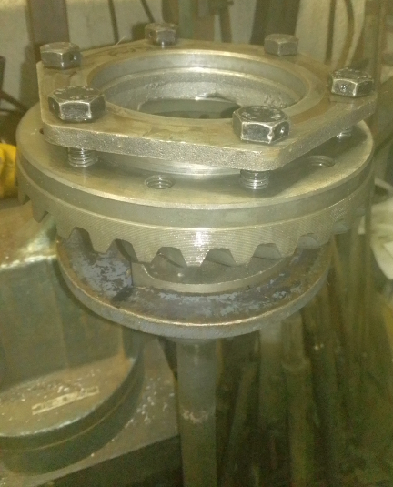
AT RIGHT: Here we're using the bolts to help ensure the ring gear is aligned for when the second carrier half is mounted, thus speeding assembly. ...Note how the bolts have holes in their heads running perpendicular to their main axis: these are for wires that are threaded through all 6 of them to ensure they don't back out, should they come lose! This is a process called "safety wire."
Due to the grave risk of cracks, and especially how common it is for them to be cracked, all units must be checked for cracks via magnifluxing. Both the one from this unit and the donor that supplied the axles were, surprisingly, found to be not cracked and serviceable!
The factory tool to support the differential carrier for this work conveniently also locks it in place rotationally to facilitate torquing the bolts (and removing them). It can be seen in these images and is mounted in a bench vice.
Once the bolts are torqued and the safety wire threaded, the entire rear-axle assembly is ready for reinstallation into the left housing half, which is conveniently mounted in a factory assembly stand. This is done before the shafts are laid in.
AT RIGHT: This differential assembly is now ready for safety wire lacing. ...We didn't manage to get a photo of that.
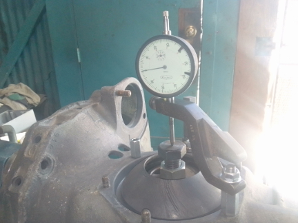
As we get to completing the assembly, it's important to measure everything. And, we have the factory tools, so this isn't so hard, but it's vital.
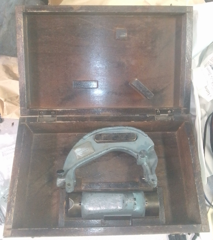
ABOVE LEFT & RIGHT: At left is the tool used to measure the differential carrier in it's box. The lower tool is the calibration gauge and the upper one is used to measure the width (factory calls it "L"), and it can do both the depth to the ring-gear and the overall width. At right is the tool used to measure the backlash, along with a pinion shaft clamp, not shown.
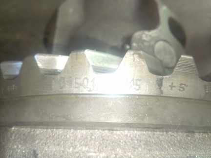
BELOW LEFT & RIGHT: At left, the ring gear is marked, providing furhter guidance (the middle number is 0.15 - the comma is the radix and the leading 0 is partially obscured by glair) while at right, the total width between the bearings is measured using tool VW 289 d. Note that the 289 d has the very often missing bolt with nut. The bolt is machined flat to ensure a good reading. And, of course, also at right are the factory bracket to hold the original dial indicator with the also often-lost extension tip - original tools help a lot!
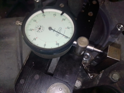
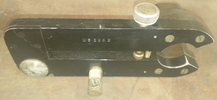
AT RIGHT: Here's the backlash tool, US 288 b with the same dial indicator installed with the standard, short tip attached. The vertical post it's touching is a tool we made, not because we don't have the factory tool to push against, but because our version of this tool is more versitle and works in more situations and in less time. Another tool, not seen, clamps the pinion shaft so it's not turning as this measure is being made.
These photos belie a heck of a lot of time spent trying different shimming to get both the backlash between the ring & pinion gears correct while also getting the bearing preload correct. Please see the factory service manuals for more about that. But, while the original preload was non-existant and we, frankly, marvel at how whoever built the box before got away with this. We managed to get the preload in the dead-center of the specification and got the backlash on the tight-end of the specification... The backlash is never one set number. Rather, you measure it every 90 degrees of the circle and never is it exactly the same everywhere. However, the permissible deviation is 0.02mm and that's what we got. And, we also got the tight end of that only 0.01mm from the ideal this ring gear says it wants! That's as good as you can get it given the shims were readily available (which they aren't!) as the shimming was only (originally) available in steps of 0.05mm.
So, from there, a bit of surface cleaning to ensure the sealant works well and then reassemble to get the pinion and input shafts in there, etc, etc.
AT RIGHT: One curious task is that you have to remove the cast end from the reverse gear selector shaft in order to install the intermediate plate on the 519 transaxle series. And here you can see it. Note that there was a lot of sunlight coming in through the skylights and windows, so getting a good photo was hard!
There's bearing thickness concerns on the pinion shaft bearing when installing the intermediate plate, so that took some measurements and calculation and then gaskets selected as the fit is adjusted via adding the right thickness of gaskets. Here, they're simply not visible, but there are FOUR 0.1mm shims between the intermediate plate and the case halves.
Then, there's the "castelated nuts" to torque, and new cotter pins installed. Unlike the tunnel type transaxles, this one is done in-situ, in the case! And this is where having the right tools really helps a lot!
BELOW: Not easily seen here is the gasket sealant. It's installed on the metal of both sides...We were running low on our favorite, so we used the also trusted "Gasgasinch", which has great properties, too, but is nearly invisible to photography!

That done, it didn't take all that long to be installing the nose cone, which the factory manuals call the "transaxle cover." Note that unlike the case halves, it's made of aluminum, not magnesium.
BELOW: Finally, we have the completed core, just awaiting axle tubes. They, too, have to be specially fitted so there's very close to zero play, but free movement. That process begins when this image was taken. Note the dark brown sealant used between the case halves is the original "Aviation Gasket", now owned and sold by Permatex; it's the original sealant used by both VW and Porsche in this era - and also used on engines through to the 912 era.
Of course EVERYTHING about a transaxle has to be carefully fitted and not only the axle tubes, but also the outer axle bearings. And so, while we don't have a lot of photos of that going on, they're pretty easy to describe.
As already noted, the tubes get however many paper gaskets between their sheet metal cover and the transaxle housing just barely permit them to move freely. Simple enough, but vital, AND a whole lot simpler with brand new axle tubes, we've learned!
The outer wheel bearing is more complex.
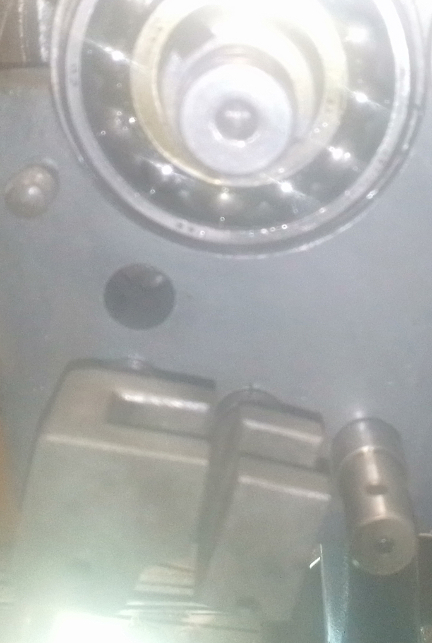
AT RIGHT: Here we have the mounted axle tube with inner spacer and bearing already fitted as well. At this point the point is to grip the outside of the race between the axle-tube end casting and the outer cover, considering the thickness of the backing plate as well. There should be about 0.1mm of "crush" on the outer race.
The purpose of the spring arm (AKA spring plate) being mounted to the end-casting is to provide a means of holding on to the axle to prevent rotation when torquing the outer cover's bolts for checking the gap, and then for doing final torquing with the backing plate installed.
Notably, both O-rings can be easily seen - the outer (larger) one is required for doing the adjustment for the outer race of the outer bearing just described and the inner (smaller) one is installed lest it be accidentally forgotten! The larger ones are captive when the backing plates are installed, but the others require the outer spacers and drums to be installed - neither of which were provided by our customer.
Not see here are installing the outer wheel bearing's seals into the end covers, doing the checks of the widths of the gaps when the covers are installed, measuring the thicknesses of the backing plates, and so forth.
Do note, though, the roll pin holding the end casting on to the axle tube; when there's no paint on it like this and the rest was painted or powder-coated, you KNOW the axle tube was removed from the end casting. In this case, there were two purposes: 1) to install the solid axle boots, and; 2) to replace the axle tubes with new ones.
From here, it's a bit of "clean-up work", attending to the little things leftover. One of those can be seen here: the clutch arm has been mounted.
The official documentation was oriented towards getting you replacement spare parts, NOT on documenting history, and so there are substantial gaps in what we can know from them and have to rely upon "those who were there." However, these people are dying off, retiring, etc, and even then, they didn't take a moment to think about some of these things we care about today... And I bring this up because the clutch arm at right is one of these possible losses of knowledge and information.
This clutch lever arm is a one-model-year-only item apparently, and even the likes of Al Zimm, super-well-known guy who was active with these "back in the day", says he doesn't know that he's ever even seen one of these! What's unique about it? It's fully splined around its entire curcumference, internally on the arm, and externally on the shaft onto which it fits, of course.
However, I spoke with Vic Skirmants, also a guy who was active with these cars back when they were new, and he says that this 1956 arm was intended as a transition item that could be used in either the earlier or later cars as they were already beginning the 644 transaxle's production work and knew a change was coming. So, a fully splined arm means it can be rotated to work for either earlier or later eras! Masterful! ... Too bad they didn't note this in the workshop manuals OR tell us how to position them for either purpose! DAMN! Missed opportunity!
However, sharp readers have no-doubt already noted the shock-mounting-arm-less axle tube end castings (the image just above - one or two - right), and deduced that this isn't going in a 1956 but rather a much eariler car!
Yes, this one is going into a 1952 production, 1953 model year Porsche. And so, its clutch arm belongs where the earlier VW arm would be, and its position is known. So, we set it to that as can be seen here, immediately above right.
BELOW: And here it is, ready for our customer to pick up and bring back to their baby!
A final note: The axle boot clamps should not be installed until the transaxle is bolted into the vehicle because the tubes invariably undergo a lot of rotation during transport and installation and these stresses should not be applied to the boots lest they leak due to this cause.
Because some people are keeping logs of VIN, engine, and transaxle numbers and then purport to tell people what someone else has, out of respect and concern for our customer's privacy, we do not publish exact serial number data of any kind on this site.