Copyright © 2007 - 2026, Coachworks For contact data Click Here.
Copyright © 2007 - 2026
Copyright © 2007 - 2026,
Coachworks For contact data
Click Here.
![]()
This page documents the servicing of one particular transaxle.
This transaxle is being done as a part of the effort to complete a 1956 Porsche 356 A's restoration.

Parts availability aside - and that's a serious problem these days - the 519 is among the hardest transaxle in the Porsche / VW world to rebuild - there are none worse, though the pre-519 transaxles are about as bad (and the younger, three-synchro VW "split case" versions are only a tiny bit easier since their synchros are easier to handle).
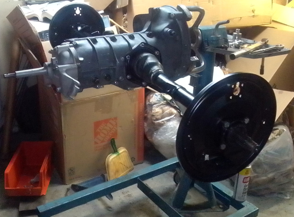
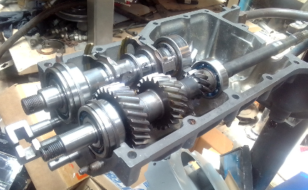
AT RIGHT: Here, this transaxle has just been completed. Note that the backing plates are not, technically, a part of the transaxle, however, we knew this all was going together soon and we might as well button it up now!
In short, the reason these transaxles are so difficult is because the design which requires both the details of the pinion shaft and differential be handled simultaneously inside a casing that doesn't provide a robust - confident and accurately repeatable - positioning of the pinion shaft. (The whole shaft assembly's fore-aft position is determined by clamping the forward end bearing to a groove in the case. ...There's a bit more to it than that, but for layman's terms, that's pretty accurate.
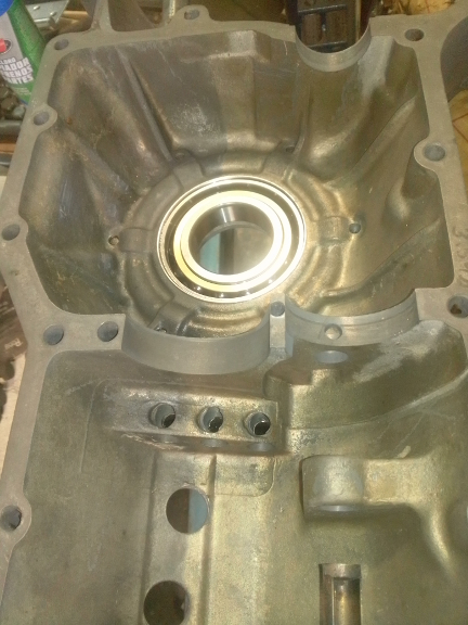
Regarding this specific transaxle, we normally take "before" photos of equipment we service but this time, we happened to be doing three transaxles back-to-back with some work going on simultaneously, and somehow we didn't get our usual shots of this one before disassembly, only these two. Note the caption.
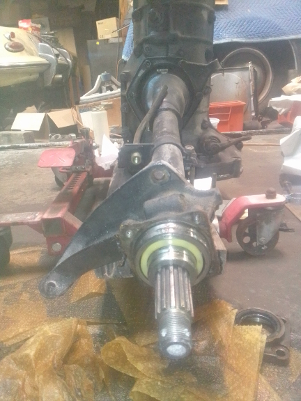
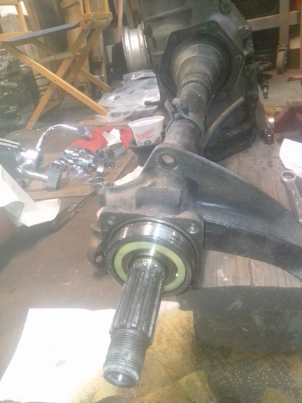
ABOVE, LEFT & RIGHT: This pair was taken to illustrate that the axle bearings were installed backwards! This was, no doubt, done because the person thought the oil could get into the bearings more easily from the other side which is open. However, the oil will get there anyway, but installed this way, the proper removal took cannot be used without destroying the bearing cages! Doah!
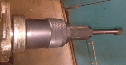
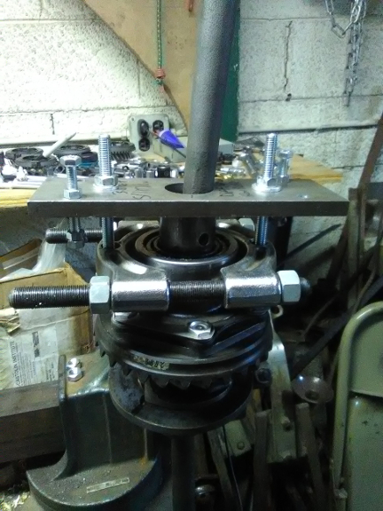
AT RIGHT: Said tool in service on this 519 transaxle.
However, even from just these first two images, we can see that the clutch cable bracket is the wrong one! Thankfully, the correct one is presently available! A few other minor details can be picked out, too.
 When
we took the case appart, we used our special press tool press tool to pull the
case halves apart by pushing on the differential, and thus PROPERLY driving
it out of the S2 bearing, but unfortunately, the S1 bearing, and, indeed, the
whole differential / axle assembly fell out of the left case half! That's NOT
supposed to happen!
When
we took the case appart, we used our special press tool press tool to pull the
case halves apart by pushing on the differential, and thus PROPERLY driving
it out of the S2 bearing, but unfortunately, the S1 bearing, and, indeed, the
whole differential / axle assembly fell out of the left case half! That's NOT
supposed to happen!
We then had to use a special setup of our tool to remove the bearing from the differential.
AT RIGHT: Here, we're using our special tooling we made for this job to pull the bearing off the assembled differential.
The bearing is supposed to be removed from the case half (or, in younger years, side cover) by heating it and the different coefficients of thermal expansion let the bearing come out on its own, but ONLY in that circumstance. The bearing fell out of the case half most likely because some fool drove it out without heating it, thereby damaging the case as the magnesium alloy is far less strong than the steel bearing. ... Some people just shouldn't be working on transaxles...
These cases are rare today and expensive. We were unable to find ANY avilable without having to buy the whole (disassembled) transaxle, and that was over $5000, plus it was in Europe! ACK!
So, we sleeved it!
In this process, you cut the bore a bit bigger, then make an aluminum ring as the magnesium material is extraordinarily expensive - you can't buy just an inch or two, or even a foot or two, of the right diameter tubing!
You then use the thermal trick again to (cold vs hot this time) to insert it with an "interference fit" with as much "crush" as you think you can get away with and insert the ring.
Finally, you bore it out to the correct size for the bearing.
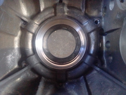
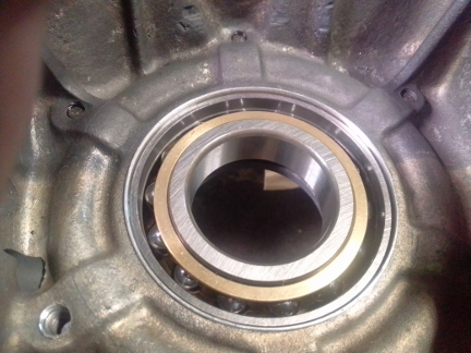
BELOW: At left, the sleeve is installed and ready, and at right, the bearing has been installed. To do this, we heated the transaxle half in an oven and left the bearing in the freezer overnight. When brought together, it just dropped right in place.
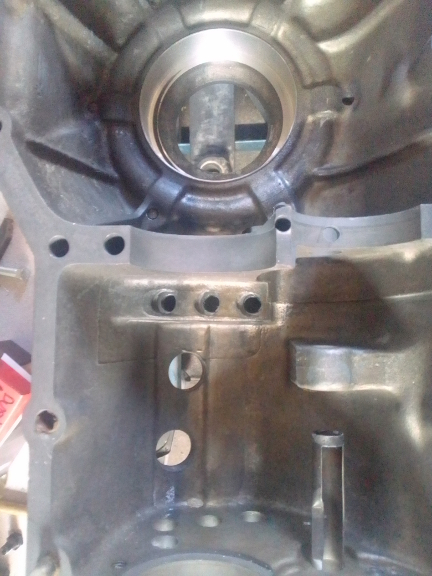
AT RIGHT: And so now the reassembly can really begin! Note that the right-most shift rail (rod) visible, protruding from the case half in the foreground, is for reverse and the end of it needs to come off before the "intermediate plate" is installed - it has to come off and go back on every time the intermediate plate is removed or reinstalled. To ensure it, the "foot end," isn't lost, it was reinstalled while the rest of the transaxle was prepared for reassembly. And it will stay on until we're ready to install the intermediate plate - which won't be long now! (Or, so we thought at the time...)
At this point, we discovered that things have changed in the supply chain since last we needed these; we had a heck of a time finding all the correct bearings - some are easy, some are incredibly difficult. It turns out that the numbers used originally to designate which bearings are used have been repurposed! This means that if you order a bearing from the correct number you MAY or may NOT get the bearing you wanted! And, we had many, many returns. We even tried sourcing based on sizes alone and had problems with load ratings and so forth. We explored all our options.
In the end, we had to have lock ring groves cut into both bearings at the "intermediate plate" (at the forward end of the input / main shaft and pinion shaft), and we eventually sourced an old-school pinion head bearing... And we now have a few brand new bearings we don't know what to do with because we didn't realize they were wrong until after unwrapping them! Doah!
Additionally, we knew we had a shortage of shims, both for the pinion and differential adjustments. More on that below; for now, lets get to the differential.
The differential disassembly was problematic from the start. Apparently the thoroughly unqualified "mechanic" who rebuilt this unit in the past didn't understand that the differential carrier is a fairly soft iron, NOT steel, and, of course, they screwed it up.
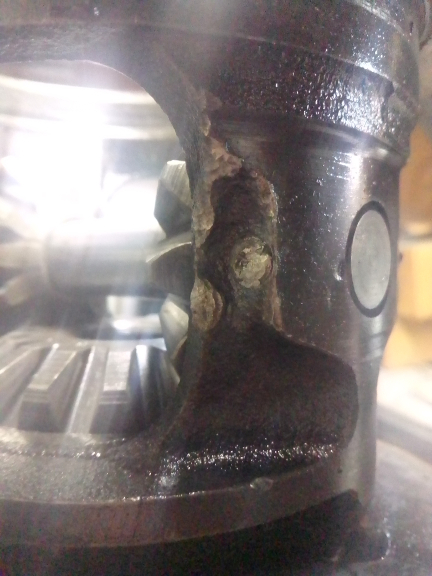
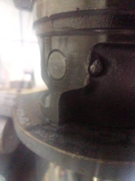
While it's true that WAY back in the 1950s, they wrote in the shop manual you were supposed to pein the ends of the spider gear cross shaft retaining pin, but this individual struck the carrier instead! The MODERN solution is to skip all that and just install a roll pin (which was probably available back then, one would think). AND, note in the image at left, they also tried to lock the spider gear cross shaft in place by using a small punch and trying to close up the hole a little - a process also called peining. However, one, the other, or both of these cracked the carrier on the left side of the pin as we face it from this end - a fact we weren't to know for sure until we had the carrier magnafluxed.
So, we had to find a new differential carrier. New is available for around $1200, last time we checked (a few years ago), but we found a good one that passed magniflux testing for about half that.
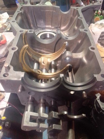
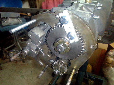
AT RIGHT: Here, the guts are starting to go together with all four bearings now installed. Note the twin lock ring groves on the two bearings on the left end of the shafts (see the text). The pinion shafrt is left without the actual gears and, notably, their bearings, until both the depth of the pinion head into the ring gear area is set and the backlash of ring gear to pinion gear is also set because otherwise, there's a lot of potential disassembly required and it's just extra work.
Even with some of the images AWOL, it's worth showing how we measure the differential:
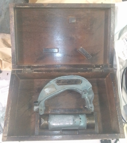
AT RIGHT: Here's our factory differential measurment tool. This tool measures the width of the assembled differential carrier and the distance to the back face of the ring gear, with the aide of two (or one moved between the locations) dial indicator with the correct length extension tip.
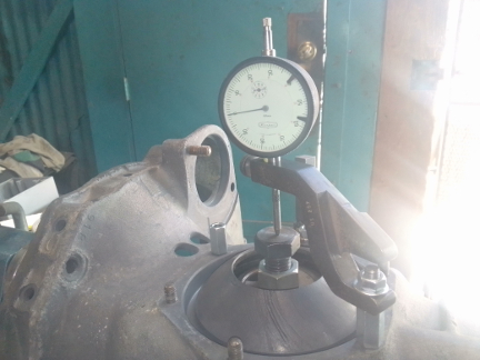
BELOW: This is how the void the differential carrier fits into is measured - using tool 289D with its companion dial indicator and dial indicator holder! (This image is from a different transaxle.)
The pinion shims were a challenge in that to make them the thickness we'd like (0.1mm and 0.15mm), they'd have to make two male / female die pairs (one for the inside diameter, another for the outside, and these are often made as a compund die to ensure they're concentric. This, of course, costs a bunch, plus they want to make quantity runs - this is the way such a dialogue starts to go wrong: "So, how many thousands do you want?" So, they're sub-dollar each, but still!
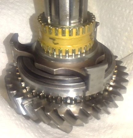
AT RIGHT: We took a LOT of photos which are AWOL, but happily this one of the second gear bearing having been installed on its race made it. Note the little rollers. There are over 50 per gear! And, they're NOT captured, so they're a royal pain to deal with. First gear is visible below it, and the three armed piece (factory calls these "manchon guides) is for the 1st / 2nd gear selection ring. Also visible is the 1st gear synchro ring, and the "hub" with the dog-teeth that the gear selction ring (factory calls 'em "operating sleeves") engages to lock the gear in engagement.
In the end, we found a way at much more cost each but for just a few, however our vendor made them a bit too small on the inside diameter and we had to have another batch made.
The differential shims were relatively easy, by comparison. The factory's strategy is one thick shim on either side, and, if and as necessary, they provided 0.1 mm and 0.25 shims to fine-tune the adjustment. This thin one is still available, thankfully, so the issue here is a lack of supply (variability) in the thick shim. And for this we decided that we can just make some thicker shims that lets us take a thick shim that's not thick enough and get closer with our shims and still fine-tune with the factory's 0.1 & 0.25 mm shims.
And speaking of the differential again, we first assembled it with the original axles, fulcrum plates, and so forth, used a roll-pin to retain the spider gear cross shaft, bolted on the ring gear, and measured our replacement differential's width and distance to the back face of the ring gear. We took photos, we thought, but they're AWOL, unfortunately. However, you would have seen in any images the roll pin and that we used the fold-over lock plates instead of threading the bolts with safety wire.
 Once
the differential was done, we waited until we had the pinion gear sorted before
trying to set the ring gear depth and backlash.
Once
the differential was done, we waited until we had the pinion gear sorted before
trying to set the ring gear depth and backlash.
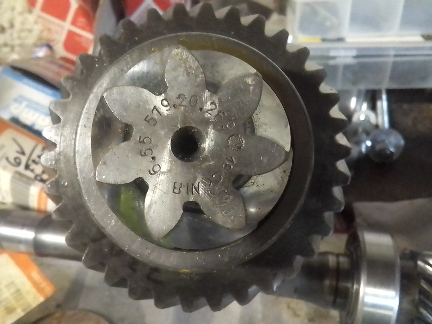
AT RIGHT: On our computer screen as we look at this, the image is about life-size, and barely visible at all are several inscriptions done by hand with a diamond-tipped engraving tool. (The month, year and part number are stamped in and not inscribed.) And it SURE looked like the pinion shaft was for a different ring gear?!
Careful analysis - via this image blown up to HUGE size showed that it had had TWO match numbers inscribed! Apparently someone made a mistake or maybe the ring gear was found bad during manufacture, and the second number inscribed, FAR weaker of an inscription, was a correct match! -WHEW!-
Prior to finishing off the axles, however, we had to deal with the fact that the pinion gear and ring gear appeared not to be a matched pair!
More missing images we'd show here if we had them are of the pinion shaft finally being fully assembled. however, first lets talk about that assembly process because it was VERY strange!
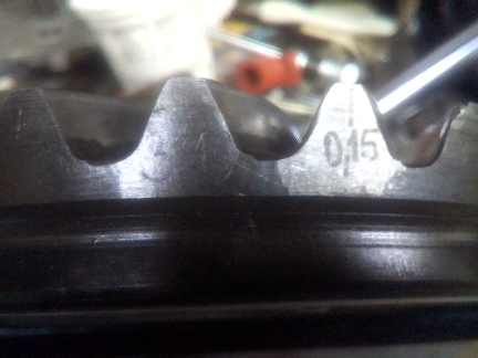
AT RIGHT: The correct backlash value for this ring and pinion pair is clearly visible on the rightmost of the inner two teeth. To its immediate left is the match number for the pinion and ring gear pair, and this number does NOT match the most easily visible of the two match numbers on the pinion head! (See image above.)
In this instance, whoever built the box left out ONE of the thick "spacers"! On later transaxles, there are five of one size - which fits over the splines on the pinion shaft - and one of each of two other sizes. On all 356 transaxles, the first five are nominally 3.5 millimeters thick and are installed on either side of each gear, including at the gear selector ring hubs. Also on all 356 transaxles, another 3.5 spacer is used on the pinion head side of fourth gear and it differs because here we're beyond the splines and so the shaft has a smaller diameter. However, only on the later tunnel types - after the 519 ("split case") series - is a thinner shim used (nominally 2mm) and on the 519, which this gearbox is, it's not used at all.
![]() It's
vital to note that the proper adjustment of the pinion on the 519 series vitally
depends on the thicknesses of the entire stack, from the bearing to the contact
faces of the gear head (or the flat faced end as that's easier to measure from).
The lock ring is what locates this and it's supposed to be accurate to within
around 0.05mm or thereabouts as that's the limit of official variables to control
it - namely actual shims!
It's
vital to note that the proper adjustment of the pinion on the 519 series vitally
depends on the thicknesses of the entire stack, from the bearing to the contact
faces of the gear head (or the flat faced end as that's easier to measure from).
The lock ring is what locates this and it's supposed to be accurate to within
around 0.05mm or thereabouts as that's the limit of official variables to control
it - namely actual shims!
Therefore, when whoever it was tried to build it missing one of these ~3.5 spacers, well, they had to make up for the difference! They used a few ~4.5 mm thick spacers, which in theory might have done it, but it was a bit shy and the smaller diameter used on the inner end of fourth gear caught on the edge of the splines and gave the IMPRESSION that the pinion was locked in place. And, indeed, it likely wasn't moving around. However, THE ENTIRE STACK inboard of fourth gear (that is, ALL the gears, hubs, spacers, shims, and the pinion head bearing itself) were free to move a good bit! Thus, we found unusual wear pattersns ... But NOT where we'd have expected them!
Remarkably, the pinion and ring gear teeth all appeared to be OK! And, similarly, all the individual gear teeth seemed OK, too! ...One has to speculate this build didn't get many miles on it! But it was DEFINITELY run, no doubt about that!
Of course, we swapped out the ~4.5mm thick spacers for the proper ones but still had a heck of a time getting the stack correct. If we recall correctly, when going to ~3.5 on fourth, it was too little but ~4.5 was too much, so used two of the later fourth gear outer spacers in the inner location and then fine-tuned with a special shim between the fourth gear and bearing.
AT RIGHT: These four parts were found by just searching around the workshop and are imaged here because they all fit the pinion shaft. At Bottom: a rear-axle outer bearing shim as found in some shim-kits. One up from bottom: a cooling fan shim that's used to adjust the fan to generator mounting plate distance. The top and one down from top: exact applications unknown - and the upper one is substantially thicker but is otherwise identical to the second from top. Note that these aren't even all the ones that can fit, just the ones we looked at as perhaps helpful in this build.
We ended up using the one that's one up from the bottom between fourth gear and the bearing at the intermediate plate.
..."When it was all said and done", replacing five spacers that are supposed to be ~3.5mm (about 17.5mm in total) with four ~4.5 spacers, you might think it would be too thick (at about 18mm), but these measures are just ball-park-figures, and the other components all matter, too. Plus, we didn't measure the original R value (distance from ring gear centerline to pinion head face) because we couldn't! Recall that early on, during disassembly, the differential just fell out, so there was no knowing what the actual build was like...
In any event, our build is also non-standard, but at least we know it's got a good shot at longevity now.
As for the build, once we got the shaft's R value (pinion head distance to differential certerline) correct, we could then set up the differential's preload & backlash to pinion gear. And, of course, the rear axle bearing preload and ring to pinion gear backlash are directly related. We got it done reasonably quickly.
Again, we lament we haven't photos of the process, but we do have some from our past to share.
Here's the backlash being checked, again using factory tools. This is the dial indicator that works with ALL the factory Porsche and VW tools of that era:
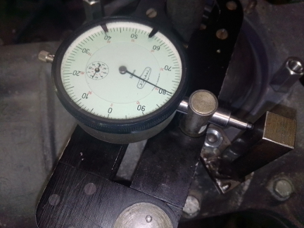
AT RIGHT: Here's the backlash tool, US 288 b with the same dial indicator installed with the standard, short tip attached. The vertical post it's touching is a tool we made, not because we don't have the factory tool to push against, but because our version of this tool is more versitle and works in more situations and in less time. Another tool, not seen, clamps the pinion shaft so it's not turning as this measure is being made.
So, then it was time to assemble the pinion shaft as noted above near the image of second gear's bearing having been installed. Oh, and of course to build the pinion shaft, the synchros need to be installed on each gear first!
Once the R&P details were done and the pinion shaft was fully assembled, we then adjusted the shift forks. In doing that work, we noticed that fourth gear wasn't rotating properly! DOAH! However, it turned out to be an easy fix: We'd put the 0.5mm shim pictured immediately above right (see caption) in the wrong order and so by just shuffling them around, we got it working correctly!
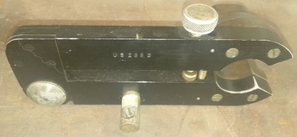
AT RIGHT: This is the tool US 288B when not in use - it's upside down! It spreads into the differential carrier and turns with it and holds the dial indicator as shown above on the part going downward in the image at right.
Now, we lubricated up the throw-out bearing cross shaft bores, the shaft itself and installed these, and mounted its arm and little pieces to keep them near-to-hand for finall installation in the car. (The arms on this year are adjustible at the shaft and knowing what orientation to attach it at is best done in-situ, inside the car!) The breather is then mounted and oriented to the correct rotation - if it's wrong, the box will dump oil on the ground!
AT RIGHT: As noted in the text below, here you can see two of the new studs - upper left and lower right - and our ingeniously simple method of keeping the pinion shaft from roating while torqing the nut! Here, the input (main) shaft's already done, and the pinion shaft has been torqued but the cotter pin hasn't yet been installed. Note that the nut threads pretty far on, so we intentionally tapped the cotter pin's ends deeply into the nut's slots to help ensure nothing ever goes wrong.
As we got close to finishing things off, we had to do some thread repair on three of the M8 threaded stud mounting holes on the nose-cone end. And, there were missing studs and we replaced three. We put in one short stud that holds the intermediate plate to the housing pair, and found one allready replated, correct-length stud (80mm) that goes through the intermediate plate. And, we made one ~100mm length stud that also goes through the IP. We strongly suspect that the two last missing fasteners were also studs, but as they thread into the intermediate plate, and as we had them available, we substituted bolts. And, of course, the holes they thread into had clogged threads, so we ran a tap through 'em.
It was then time to mount the intermediate plate, put the nuts on the ends of the shafts, and install the reverse components, starting with the reverse gear casting on the end of the shaft dedicated to reverse, followed by installing the nose cone...
We used a depth-gauge to set the bearing crush for the pinion (and main) shaft bearing (it's done by using the correct thickness / amount of paper gasket(s)), then installed the reverse gear "foot" discussed elsewhere.
We apparently misplaced our pinion shaft lock tool, so instead, note in the image above right our ingenious method of solving that problem! Simple! Conveniently, the gear has two M8 threaded holes to aid removal. We use these for not only this lock tool but also for the better, more versitile one that is a bar that bolts on to both of these threaded bores.
Following this, we slathered grease inside the gear selector feet, on the gear selector shaft headed to the shift linkage at the front of the car, the intermediate reverse gear's support shaft and so forth, then mounted the nose-cone.
After threading in the drain and adjustment plugs, we ended up with this:
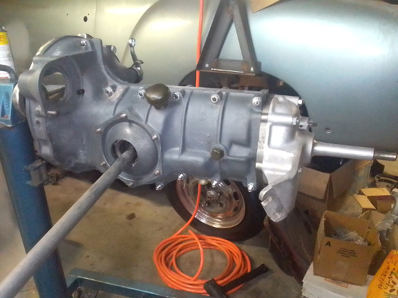
AT RIGHT: Here it's just about done, the only significant work remaining is installing the axle tubes. As noted above, the clutch arm will receive final installation when installed in the car.
Now it's time to get the axle tubes mounted and begin installing the brakes and drums!
A final note: The axle boot clamps, if original straps, should not be installed until the transaxle is bolted into the vehicle, and if replacement style band clamps, not tightened, because the axle tubes invariably undergo a lot of rotation during transport and installation and these stresses should not be applied to the boots lest they leak due to this cause.
Because some people are keeping logs of VIN, engine, and transaxle numbers and then purport to tell people what someone else has, out of respect and concern for our customer's privacy, we do not publish exact serial number data of any kind on this site.